Category Archives: Platform

Revit Basics – Orient to View

This is an excerpt from an article that I wrote for AUGIWorld.

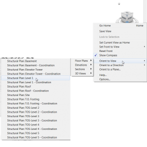
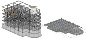
Models routinely become large or complex over the life of a project, and consequently a Revit user will occasionally want to isolate, in 3D, a certain area of the model or a particular group of elements.  The novice Revit user will then begin the tedious task of hiding elements to achieve the desired view.  Of course numerous options are available to quicken this process, such as toggling the visibility of different categories of elements, temporarily hiding/isolating elements in view, applying ghosted settings, manually adjusting section boxes, and perhaps even filters and/or worksets. This approach will eventually work; however, the task of isolating a particular section of a model can be quickly achieved by using the Orient to View command, which is found by right-clicking on the View Cube, shown in the first image.  The second image shows a floor that has been isolated via the Orient to View command.

The way this command works is to adjust the section box such that it mimics the view range and the crop region of the selected view.  To return to seeing the entire 3D model, either turn off the section box in the view properties, or manually stretch it back.

Revit Basics – Create Similar

This is an excerpt from an article that I wrote for AUGIWorld.

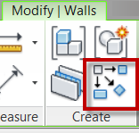
Until Revit 2010, the only easily accessible location to activate the Create Similar command was in the right-click context menu after a single element is selected. Revit beginners probably didn’t even know the command existed.  Create Similar is now available on the Modify Tab, but remains grayed out until a single element is selected.  The inquisitive Revit novice may have discovered this command’s function by hovering over it and reading the tooltip, but others may not have noticed it and don’t know it exists.

The Create Similar command activates whatever command is necessary to create a new instance to match the type of an existing element.  For example, selecting a wall and clicking Create Similar activates the wall command and sets the type of the wall to match the one selected;then the user maydraw another wall instance.  This command is particularly useful for several reasons.  It matches an element’s type without the user having to know that type, and without having to navigate through the (occasionally long) Type Selector looking for something specific.  One may just copy elements to achieve a similar outcome, but then the user is left modifying, moving and altering the new instance after it is placed.  Also note that copying will not only copy the desired element, but also any hosted elements, i.e, copying a wall will also copy all of the doors and windows in that wall.  While extremely useful, the Create Similar command is not without its flaws.  It only matches type properties, not instance properties – or at least not all instance properties – so, for example, it will create a wall of the same type, but not of the same height.  Strangely, however, it will match location line settings, which is an instance property.

Revit Basics – Tab

This is an excerpt from an article that I wrote for AUGIWorld.

“Press tab” is likely one of the phrases beginner Reviteers get tired of hearing.  It is common knowledge that the tab button can be used to cycle through elements to enable the selection of a specific element in a congested area.  What is lesser known, or at least lesser-used, is that pressing shift + tab will cycle through the elements in the opposite direction.  Knowing this small item would prevent this very familiar occurrence: “Tab, tab, tab, tab, tab, shoot! I skipped the element I wanted….tab, tab, tab, tab….”

Just in case it has not been said enough, the following is a list of some of the useful applications for the tab button: cycle through elements in a congested area; instead of just one segment, select a chain of walls or lines; select only a segment of chain of walls (select the first one and then press tab while hovering over the last desired segment); instead of one at a time, select connected beams all at once; cycle through snap locations (end point, intersection, etc.); get to objects in a linked file to see the properties.

Space Frame Panel by Pattern

In a previous post I added a curtain panel by pattern to a mass family, this family was set up to be a space frame.
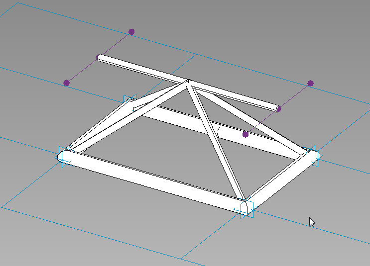
In this post I will get into how this family was created by using the curtain panel pattern based (CPPB) family template.  With any CPPB family it is crucial to pay attention to the workplanes that are being used, most of the times these will either be points or reference lines.  My first few attempts at CPPB families I didn’t pay as much attention as I should have and struggled getting the results that were needed, by paying attention to that little detail would have saved a ton of headaches.

When a CPPB family is open there will be some default ref lines and adaptive points, depending on what the tile pattern grid is set to will determine how many of each there are.  By default it starts with Rectangle, if a different pattern is needed then select the perimeter of the blue grid on the screen and change it in the type selector.
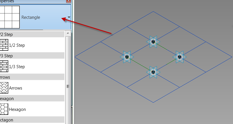
In the space frame family Rectangle is what I needed, so no changes were necessary.  The first thing that was required with this family were some reference points.  These reference points need to be related to the Adaptive points, to do this the workplane of each adaptive point must be selected before placing the ref points.
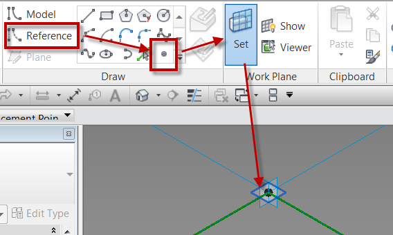
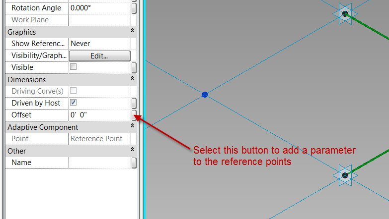
Once the workplane is set place the ref point directly ontop of the adaptive point, do this for all four corners, or adaptive points.  One that is done select the ref points that have been placed (filter is a great tool for this) and  add a parameter for the offset property.
The end result should look like this…
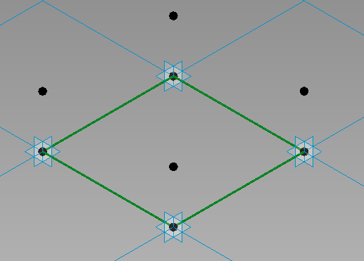
The next step was to draw a reference line from point to point.  The critical step in this is to make sure the 3D snapping is turned on while selecting the the reference points.
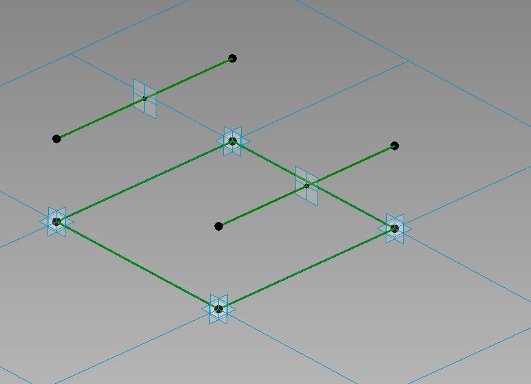
Next draw another ref line between the two new ref points.  Again making sure that 3D snapping is turned on.  Add another ref point to the middle of this line.  Draw 4 new ref planes from the corners to this ref point. 
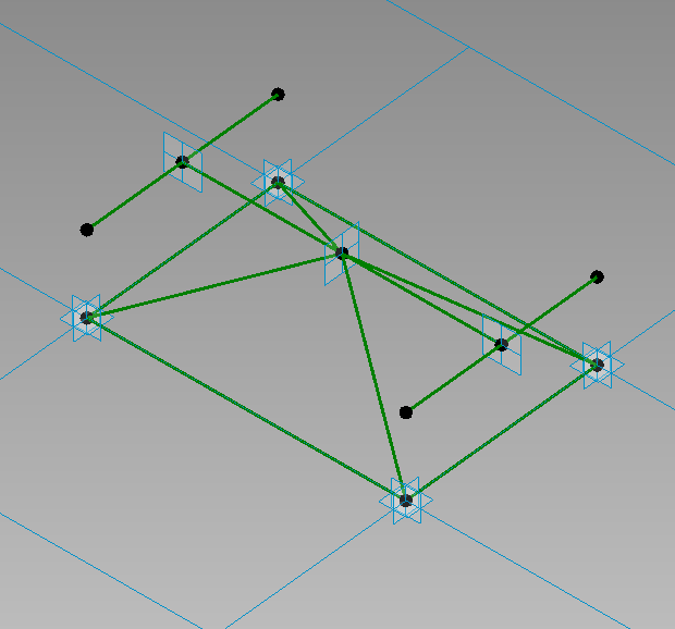
Now that the rig is done m1ake sure to flex it, move the adaptive points up and down, also select the tile pattern grid and change the properties of the horizontal and vertical spacing.  At this point in time this rig could be applied to a mass, although nothing will be displayed since only reference objects have been used. 

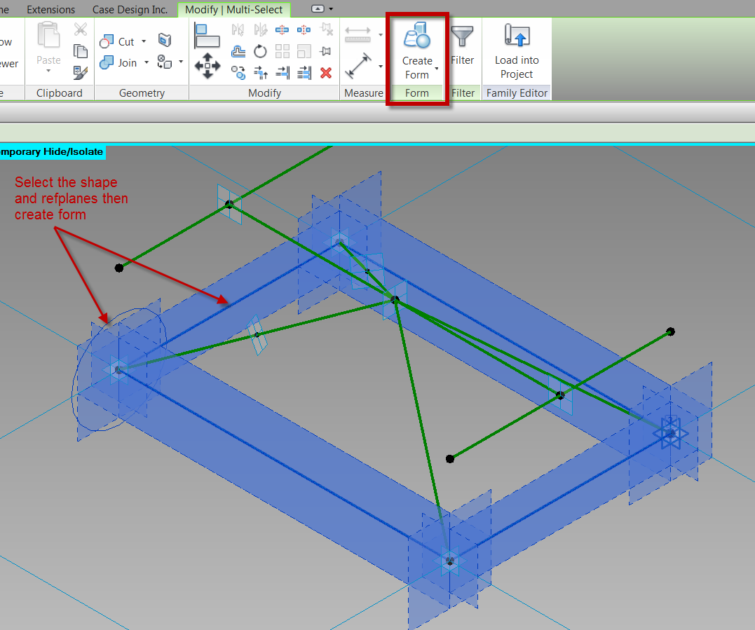
Now sweeps will be needed to represent the frame itself, this can be done in many different ways, this post is just going to use model lines swept along the ref-planes. To do this I will keep making one of the ref-points my workplane then draw a circle on that plane (paramatize as needed), select the circle and the appropriate ref-planes, then select create form.
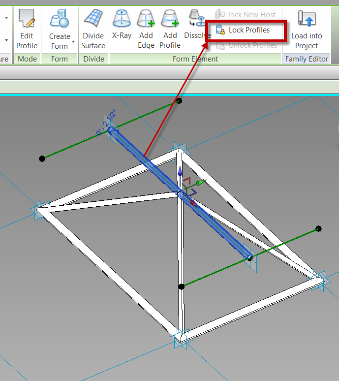
 Note:  When a sweep follows only a single path, and there are parameters assigned to the shape, the shape can vary along the path.  For these instances select the sweep and select the Lock Profile button.
Please post any questions or comments if you have any.


Parametric Massing with Ellipses

The BIM TroubleMaker posted about making a parametric ellipsoid in Revit/ Vasari and Zach Kron posted his version of this.  It was great timing as I was doing a comparison take on a similar type issue.  Dezi was creating an elliptical shaped form in Rhino/Grasshopper that could represent an arena or stadium for her company and I thought I would do something similar in Vasari at the same time so we could compare.

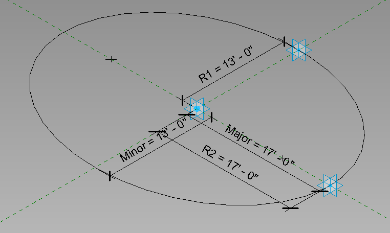
I started with a generic adaptive component family, and created an ellipse family similar to the one Zach had shown.

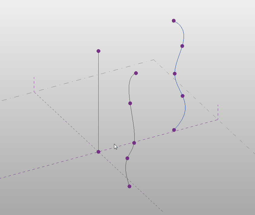
I then loaded that into a mass family.  In the mass family I created two splines, one on the XZ axis and one on the YZ plane.  To create the splines I used Reference Points hosted to the two different vertical ref planes. I then used Spline by points to create the splines. I then created a vertical reference line at the intersection of the two reference planes.

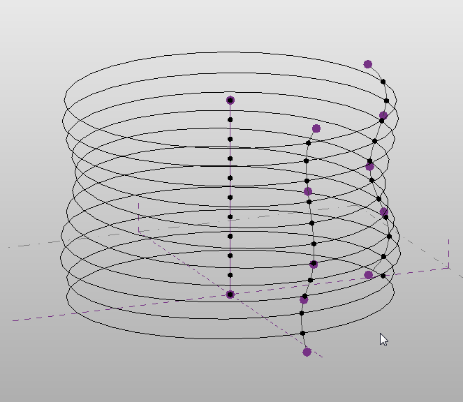
When placing the ellipse family I hosted it to it to the vertical reference line created earlier.  I then selected the placement points of the ellipse and picked the splines as new hosts.  To copy the ellipse up I selected the adaptive point at the center of the ellipse.   After copying that family up a few times I had the frame work for my mass building shape.

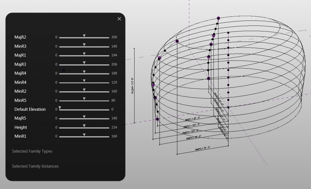
I decided that it would be nice to use the Vasari Sliders to adjust the mass so I added parameters to the reference points that made up the splines.

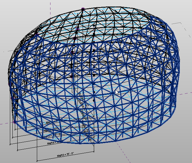
Once this was finished I created a Curtain Panel Pattern Based family that kind of represented a space frame, loaded that in to the mass and divided the surface.  Another post on this later…

That is what I came up with.

I quickly changed the ellipse shape to a rectangle but kept all the same parameters, loaded that into the mass family and changed every other family to a rectangle added my space frame pattern to only a portion of the mass and came up with this shape…

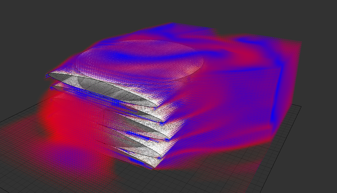
Ran the wind loads from Vasari onto the entire mass and got this…