Category Archives: Revit

Revit Posts

Spot Slope Revit

While helping set up a template with a client there was a discussion on how the graphic should look for the spot slope symbol, hence this post.

While  placing a spot slope there is an option to change the graphic representation to be either Arrow or a Leader.  However this option is not available in a plan, only vertical views such as sections.  This can also be done after placement in the properties dialog.

SpotSlopeTriangle

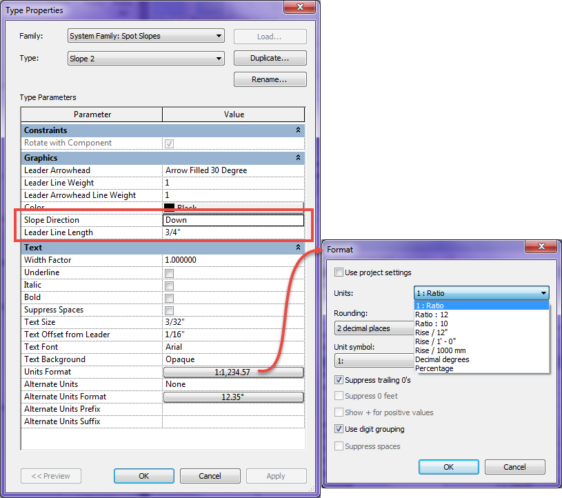
The type properties for spot slopes also allow for more options and variations on the display as well as the units:

  • Slope Direction allows for the slope to point down or up, however if the triangle option is used then it just changes the insertion point
  • Leader line Length changes the length of both the arrow and the triangle option
  • Similar to other dimension types the units format can be changed.  With slopes some firms like to display roof slopes with a Ratio/12 while displaying sloping floors with a ration or percentage.  By duplicating the slope type all of these options can be available.
  • Using alternate units will allow for Ratio as well as percentage or whatever combination in needed

SpotSlopeProperties

Analytical Model

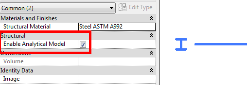
In preparation for my session on Structural Tools for Architects at BIM Workshops in Anaheim I thought of a nice tip that would be a good blog post.  When discussing structural tools inside of Revit I have heard the comment a few times that the model slows down once structural members are added.  If the members being added are K series joists or something similar then it could be due to heavy families.  Never the less what is also adding to the speed issue is the fact that all structural member, by default, have analytical properties attached to them.  Unless your firm exports out the structural members to an analytical program this feature isn’t needed.  To resolve this issue after the model has been created select all structural columns, beams, foundations etc and uncheck “Enable Analytical Model”.  If this is unchecked before placing an element that setting will be remembered and any element placed after, thus eliminating the need to keep unchecking as the model develops.

Enable_Analytical

The real tip here is to open your company template place a structural column, beam, brace, floor, wall and all three foundation types, before placing each type uncheck the “Enable Analytical Model” then delete the elements.  Your template has now been set to not have analytical model enabled thus possibly speeding up future models.  The only nuance is any member as part of a beam system or truss will still have the analytical model associated to it.

Revision tags rotate with component

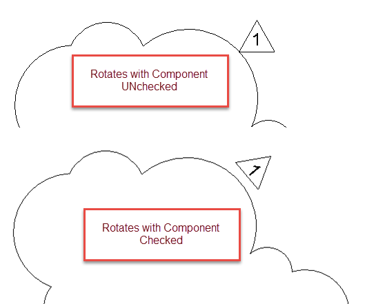
The other day while in training I found a subtle nuance to revision tags. If rotate with component is checked then the tag rotates with the curve of each bubble.  I know this option only works with draw type elements such as walls, beams, footings etc. (See Steve’s posts older, newer). I thought this was new to 2015 but found out it goes back a few releases. I am not sure why a firm would want the tags to be printed at varying angles but this option is available.

RotatesWithComponent

Sizing Reference Planes

I was doing some work with The Ant Group doing some detail work when Jim Balding (JB) mentioned a tip that I can’t believe I hadn’t been using for years.  When I create family content I am very specific about making sure the reference planes aren’t longer than needed, centered in the family etc., especially when working with detail components or generic annotations and tags.  I have family templates for most family types, my detailing template has been set such that the reference planes are centered, equal length and around 4″ (100mm) in length.  When I start a family from this template on of the first things I do is unpin the reference planes and stretch each end to the desired length for that component.  JB asked why I didn’t use the scale command?  He showed how he uses scale by selecting the reference plane(s) and scaling it from the center point, clicking the end then clicking again at the desired final length.  This really is a great tip when both of the reference planes need to be sized equally.


Windows Explorer/My Computer Columns

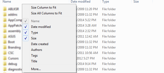
I previously posted about how to use the windows column filter to display what is needed.  I thought there should be a follow up post on how to change the display of the columns as well.  If you right click on a column header there will be a context menu that comes up allowing for a few options.  One I use often is Size All Columns to Fit, depending on what I am looking for sometimes I will select the More… option and add additional columns to see properties that are otherwise not visible.  Plus I have been in the habit of adding tags, titles etc when in Word or Excel, this way I can sort by these values in Windows Explorer.

Windows_Explorer_Columns