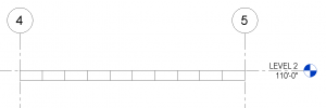
I was recently doing a quick little job for a client and in modeling the structure I needed to show a 2×4 wood framing member turned flat, so I used the OOTB 2×4 and set the Cross-Section Rotation to 90 degrees. The following is what I got.
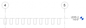
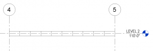
Since I wanted the top of the framing to align with the level, and the above was the result, I was reminded that the cross-section rotation’s base point is the intersection of the workplane and the Lateral Justification, so I changed the Lateral Justification to ‘Side 1’ and got my desired result.
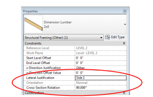
This got me thinking – what if I had wanted to move the framing more than just a little? It is a known quirk that the z-direction offset doesn’t work quite right when the cross-section rotation is set to anything other than zero, but I haven’t seen any documentation to explain what is really going on so I thought I would figure it out.
The conclusion is this: assuming the cross-section rotation is set to a value, a, if you enter a value, z, into the z-direction offset, the member will move as follows:
Vertical movement = z*cos(a), where up is positive
Horizontal movement = z*sin(a), where left is positive
I could paste a ton of screen shots here showing a bunch of variations, but I encourage you to go play with these settings and see what happens. Take particular note of the fact that cross-section rotation values greater than 180 degrees causes positive z-direction offsets to cause movements in the negative directions.
So what is the solution? I would suggest using the start and end-level offsets for z-direction movement. However, if there is a reason why that is impossible, or if you just want to test it out, the following equations will produce desired results.
For a desired vertical offset, z, a cross-section rotation, a, and assuming no horizontal movement is desired:
In z-direction offset enter: z / cos(a)
And then move the framing member to the right this amount: z*tan(a)
For a workplane that is not horizontal, the above equations work if vertical is taken to be perpendicular to the workplane and if horizontal is taken to be parallel to the workplane. To get global horizontal and vertical movements, the angle of the workplane would have to be considered, as would the cross-section orientation (Normal vs Horizontal) since each case would require different equations. Since this topic seems to be complicated enough, I will not go into any more detail on non-horizontal workplanes.
Given my affinity towards math and families, I would love to be able to incorporate these equations into the framing families (since the equations are valid for a 0 degree rotation too), but of course none of these parameters are available until after the element is loaded into a project, so I will put that on hold for now….but I reserve the right to revisit this idea!

