Tag Archives: Family

Center Mark Visible

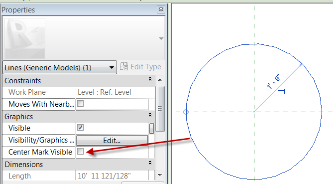
While creating some families this week I made a note to show a simple feature of circles that is extremely beneficial yet easily missed.  When using a circle in a parametric mass the circle may need to move with other items this can be accomplished by turning on the Center Mark Visible parameter. Selct an already drawn circle and in the properties check the “Center Mark Visible” option.


This will allow the align command to be used so that the center of the circle can now be locked to the Reference Planes or Lines.

Adaptive slab edge

While training a client today the question had come up of how do you do a slab edge when the slab isn’t flat?  This can always be done as an inplace family sweep with a defined profile, but as we all know to many in-place families have a tendency to slow Revit down.  So we went through the process of creating an adaptive family.  The only complaint I have is the limited categories that adaptive components can be, so in this case we left it as a generic model so that it can host rebar.

Start with the Generic Model Adaptive  template, then change the category if desired, we left ours as a generic model. 

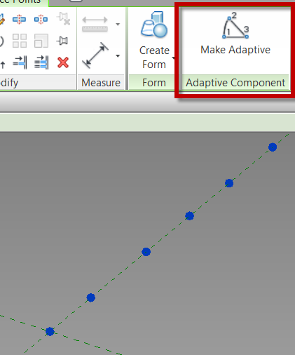
Place ref-points as needed in the view, select the ref-points and change them to adaptive in the contextual ribbon.

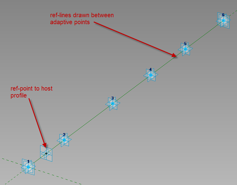
Draw ref lines from the first adaptive point to the second to the third etc., make sure 3D Snapping is on before drawing.  Next draw one ref-point on the ref-line, this point will be used to host the profile.

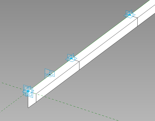
Since profile families can’t be used inside of an adaptive family create a generic model using model lines to be the profile of the thickened slab, load that into the family and place it on the ref-point.  Select the profile family and map the parameters to parameters in the adaptive family.  Select the profile and the ref-lines then create form.

This is what we had come up with instead of in-place families.  Comment if this works for you or not.


Space Frame Panel by Pattern

In a previous post I added a curtain panel by pattern to a mass family, this family was set up to be a space frame.
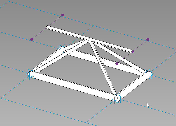
In this post I will get into how this family was created by using the curtain panel pattern based (CPPB) family template.  With any CPPB family it is crucial to pay attention to the workplanes that are being used, most of the times these will either be points or reference lines.  My first few attempts at CPPB families I didn’t pay as much attention as I should have and struggled getting the results that were needed, by paying attention to that little detail would have saved a ton of headaches.

When a CPPB family is open there will be some default ref lines and adaptive points, depending on what the tile pattern grid is set to will determine how many of each there are.  By default it starts with Rectangle, if a different pattern is needed then select the perimeter of the blue grid on the screen and change it in the type selector.
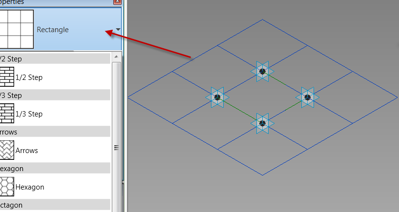
In the space frame family Rectangle is what I needed, so no changes were necessary.  The first thing that was required with this family were some reference points.  These reference points need to be related to the Adaptive points, to do this the workplane of each adaptive point must be selected before placing the ref points.
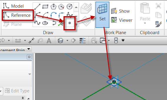
Once the workplane is set place the ref point directly ontop of the adaptive point, do this for all four corners, or adaptive points.  One that is done select the ref points that have been placed (filter is a great tool for this) and  add a parameter for the offset property.
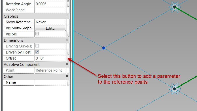
The end result should look like this…
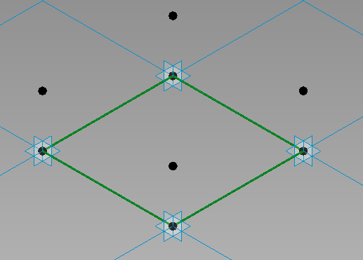
The next step was to draw a reference line from point to point.  The critical step in this is to make sure the 3D snapping is turned on while selecting the the reference points.
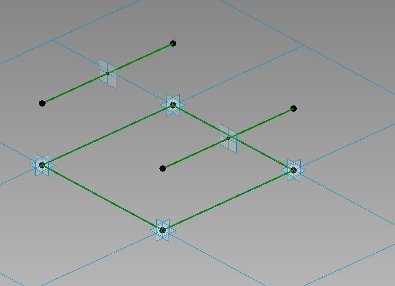
Next draw another ref line between the two new ref points.  Again making sure that 3D snapping is turned on.  Add another ref point to the middle of this line.  Draw 4 new ref planes from the corners to this ref point. 
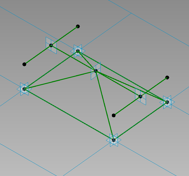
Now that the rig is done m1ake sure to flex it, move the adaptive points up and down, also select the tile pattern grid and change the properties of the horizontal and vertical spacing.  At this point in time this rig could be applied to a mass, although nothing will be displayed since only reference objects have been used. 

Now sweeps will be needed to represent the frame itself, this can be done in many different ways, this post is just going to use model lines swept along the ref-planes. To do this I will keep making one of the ref-points my workplane then draw a circle on that plane (paramatize as needed), select the circle and the appropriate ref-planes, then select create form.
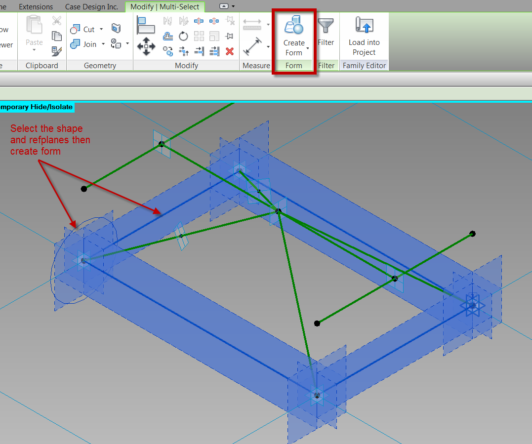
 Note:  When a sweep follows only a single path, and there are parameters assigned to the shape, the shape can vary along the path.  For these instances select the sweep and select the Lock Profile button.
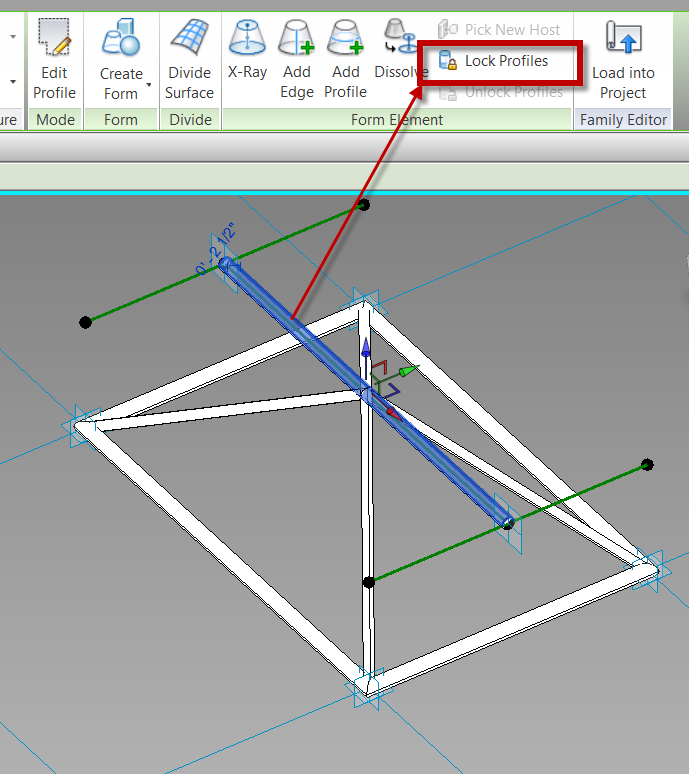
Please post any questions or comments if you have any.


Revit Technology Conference

Late last night Dezi and myself received emails that our abstracts were accepted by the RTC committee and we will both be teaching one lab and one lecture style sessions.  Since we both love RTC we were excited and now get to start working on our handouts.  I have listed our sessions below.  If you haven’t already signed up for RTC I would hurry there aren’t many spots left.

Dezi’s sessions:

Family Lab: Cuts with Voids” as a 60 Minute LAB in the Structure stream, Intermediate level.

  • With the release of Revit 2012 we were gifted an option to allow families to be cut by other families.  This seemingly small feature creates many possibilities for increasing the precision and accuracy of our Revit Structure models.  This lab will share examples of how this feature can be utilized in a structural beam family to create a beam pocket, in a precast spandrel panel with a sloped top, and in embed plates that need to cut more than one element.  Following the examples, the lab will go step-by-step through how to create one of the aforementioned examples

Integrating Revit Structure with Analytical Software” as a 75 Minute Presentation in the Structure stream, Intermediate level.

  • When it comes to analytical software there are numerous options in which software to use, and how exactly to utilize that software with a Revit model.  This session will cover when Revit models should be exported to analytical packages, how best to prepare a Revit model for use in an analysis software and will be a comprehensive overview of the different analytical software options, including RISA, RAM, Fastrak, etabs and Revit Storm.  We will compare and contrast the different software packages and look at benefits, drawbacks, similarities and differences among them.  This session will be an balanced look at these software packages from the perspective of the end user

Brian’s sessions:

Detail Management in Multi-Building Projetcs” as a 75 Minute Lab in the Architecture stream, All Levels (Forums etc.) level.

  • Working on campus projects, strip malls or any type of multi-building project inevitably brings up the discussion of how to manage the details.  Often a major driving factor in choosing how to manage the details depends on if all of the buildings will be included in one set of construction documents, or if each building will be a separate set of documents.  Based on the project and which of the two previously mentioned approaches is selected, there are a number of strategies that can be implemented within Revit to help streamline the construction document process. This class will cover a few scenarios of multi-building projects and will discuss which approach to detail management may be the most appropriate.  In addition the session will reveal and discuss the pros and cons to each approach such that the attendees will be able to apply the most appropriate strategy to their own multi-building projects.

Navisworks for the Designers and Engineers” as a 60 Minute LAB in the CCFM (Construction, Coordination, Facility Management) stream, All Levels (Forums etc.) level.

  • Navisworks is commonly used to check for interferences and collisions, however, this software can also be leveraged as a powerful marketing tool.  This session will demonstrate how to expand the applications of the Navisworks software.  In order to use Navisworks for marketing one must first understand processes such as using search sets for up to date selections and using the consistency out of Revit to expedite the use of search sets.  Once this is achieved, the building may then be quickly and easily displayed in many different ways and animated using timeliner, both of which can be useful marketing tools.  This session will discuss all of these items and will share an actual project where these Navisworks procedures and tools were utilized for marketing purposes.