Category Archives: Revit

Revit Posts

Vertical Face Based Template

I had mentioned this tip to a bunch of speakers at the BIM Workshops and they had never heard of this so I figured it should be a post, especially since one of them came up and gave me a kiss on the cheek.

When creating face based families the biggest complaint I hear is the fact that if the element is going to be placed on a vertical face, in the family the front is the plan view.  I agree this can be confusing, so why not create a vertical face based template instead of using the OOTB horizontal face based template.  Impossible you might think, well up until a year ago I thought so too, until  I learned about a workaround on changing a wall, ceiling or floor based family to a face based family from our local user group (RoMBIS).  Note you will have to have Revit MEP or Revit for this tip to work, if you have Revit Architecture or Revit Structure then you will have to download my version.  The thing I noticed when using this tool is that if I converted a Wall Based element then the surface it uses as the face is vertical.  This is when I decided to use these steps to create my own Vertical face based family.  I haven’t tried but I am sure the same thing could be achieved for an upside down face if a ceiling hosted family was converted.  However I will save all my readers the headache and post the file for download for everyone to use.

FaceBasedVertical

Here is the BD Mackey Face Based Vertical Template, there is an additional reference plane “Actual Face” as well as a parameter “Offset from Surface”, as I always build in a face offset for my hosted families.


Loading Family Quirk

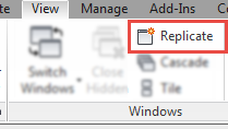
I have a client that swears he is diligent when it comes to not opening a bunch of views when working in Revit.  He kept telling me that Revit was automatically opening views on him.  In this case both of his statements were true.  A little known feature of Revit it the capability to “Replicate” a window.

Replicate_Window

This feature has been there for a long time and I can honestly say I don’t think I have ever seen anyone use this tool.  Yet the help file describes it nicely:     This tool is useful if you want to pan and zoom on certain areas of the design, while also viewing the entire design in another window. (Use the Tile tool to see both views at the same time.) Any changes that you make to the project in the new window also display in other windows of the project

It keeps users from having to duplicate or create multiple views in order to work and see multiple parts of a model.  I personally have used this feature, not frequently but effectively.

In this case the quirk came into play when my client was working in a sheet with the a view activated, this also happened to be the only thing open in the project.  Then while editing a family the “Load into Project” button was used.  Since Revit could see the user was in a view but the sheet was open it Replicated the active view.  While he kept editing the family and hitting reload, each time a replicated view was created, thus causing him to have 15 additional views open.  In a larger project the only way to recognize this easily is by the view name, it will have the view name followed by a : then number i.e. Floor Plan Level 1:15

Hopefully now you will understand while there are View Gremlins in your Revit project opening up excessive views, or at least the ones with the :## in the name.


Random Click Revit Drag End

I have a term that I have coined the “Claw” while in Revit.  It relates to when a user is trying to move the end of a line based object (i.e. Grid, Wall, Beam) and they zoom in to find the grip and then while holding the mouse button, try to pan or zoom while using the middle mouse.  My tip is to drag that grip outside of the view window, for instance to the ribbon or properties pallet etc., and then release the mouse button.  The objects grip can now be moved without having to hold the mouse button down, hence allowing the user use their index finger to zoom or pan.  Once the objects grip is in the correct location click the mouse button to place it’s location.


This saves users from having to “Claw” their way through the file.

Random Clicks Windows Scroll Bars

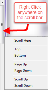
A while back I had accidentally right clicked on a scroll bar, and I noticed a dialog box come up that I had never seen before.  It allows for ANY windows scroll bar to be moved to the top, bottom, current location etc..  This is a small little tip that I use a lot when I have scrolled to the bottom and want to get back to the top, especially in the Project Browser for Revit.

Windows_Scroll_Bar


Adaptive Component Water Volume

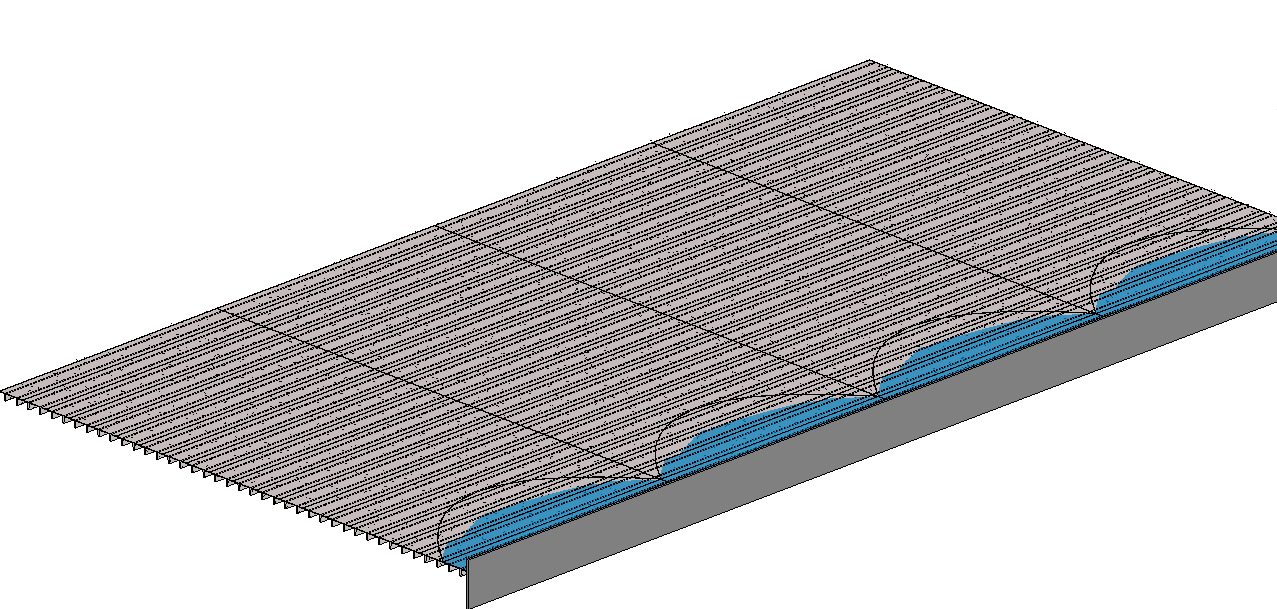
Dezi was working on a project where she had to figure out the amount of water that was accumulating in a failing double T.  Of course she approached the problem as an engineer and incorporated a lot of math into the family.  I decided that was something best left to an engineer and I decided to take advantage of that intelligence she had incorporated into the double T family and create an adaptive component to display the water graphically as well as extract volume from the family.  It is hard to see in the picture but all of the double T’s are sagging and the adaptive “Water Volume” family is reacting to the as well as the depth of water.

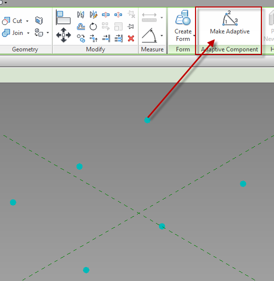
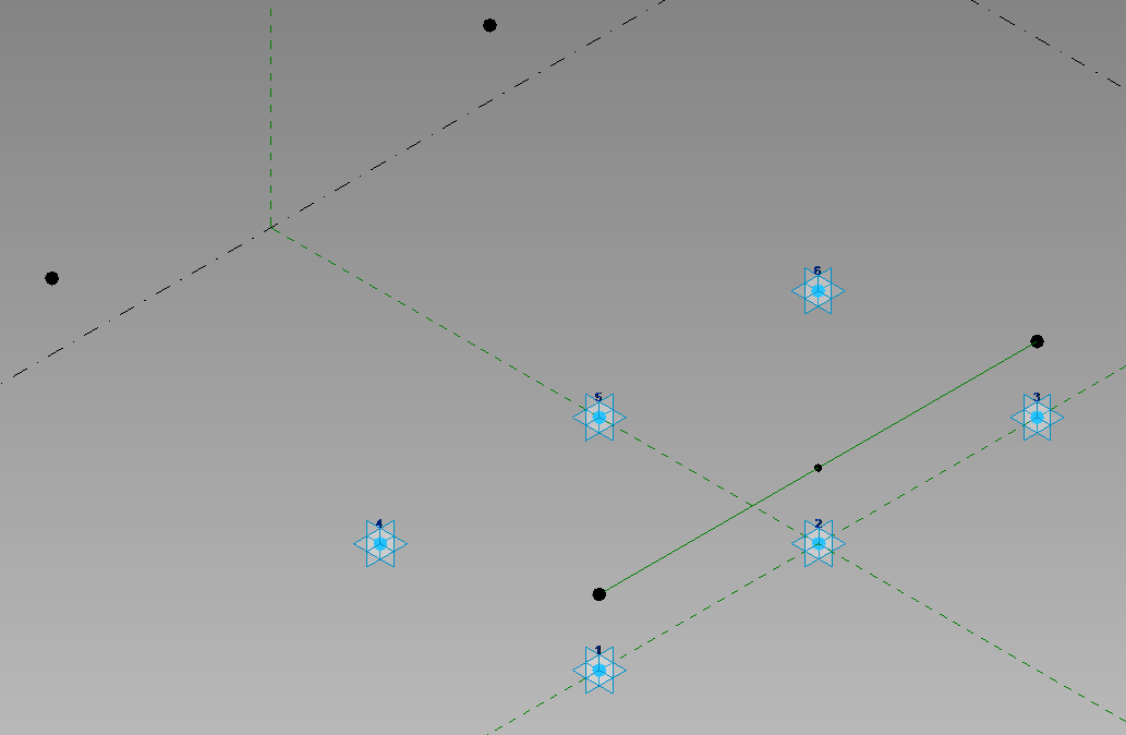
I started with a Generic Model Adaptive for this task.  This family was going to be controlled by the ends and middle of 2 separate double T’s. I placed 6 reference points on the level.  Once those are placed select them and change them to adaptive points.

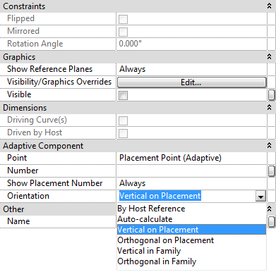
Once the points are made Adaptive new properties will be available.  Orientation is a key value to pay attention to, in this case the points need to be changed to Vertical on Placement.  If this is not selected then the form will be allowed to go any direction, we want this form to always be vertical.

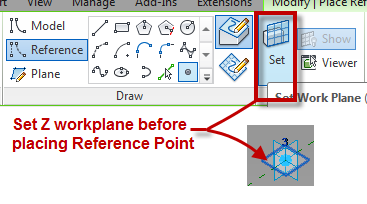
The second step was to host a reference point onto point 1 & 3. It is critical that the “Z” work plane for each point be set before the point to be hosted on it is placed.  To do this use the Set Work Plane button then select the appropriate plane on the point.

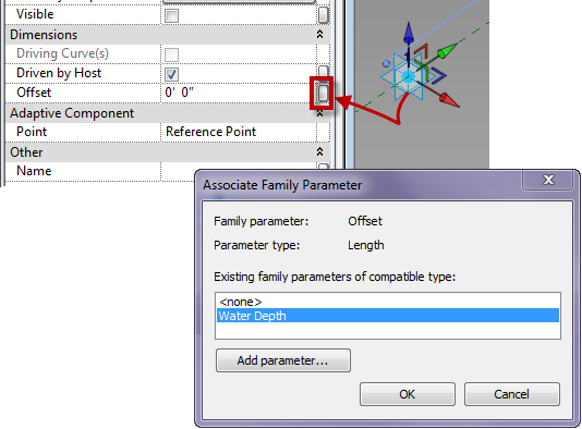
Once those points were created I mapped a parameter (Water Depth) to the offset value of the points.

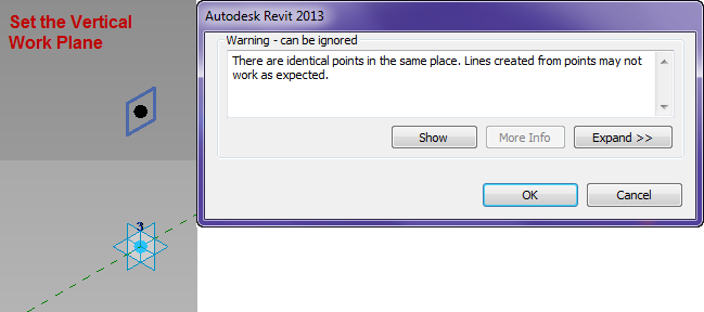
Next I associated a point to each of those points on their vertical work plane, clicking ok to the warning dialog.

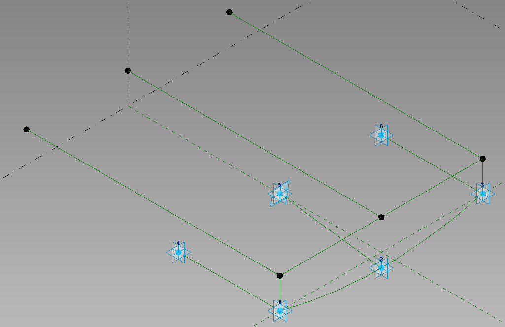
I then mapped a parameter to the offset of those points. so that they will go back towards the other points.  Next draw a reference line between the points hosted on adaptive 1&3, then place a reference point at the midpoint on the reference line.

Host another point on the point hosted on the center of the reference line and associate a parameter to the offset value of this point.  Then connect the points with Reference Lines (as per the image below), making sure 3D snapping is turned on.  Draw a spline through points use the adaptive points 1,2 and 3.

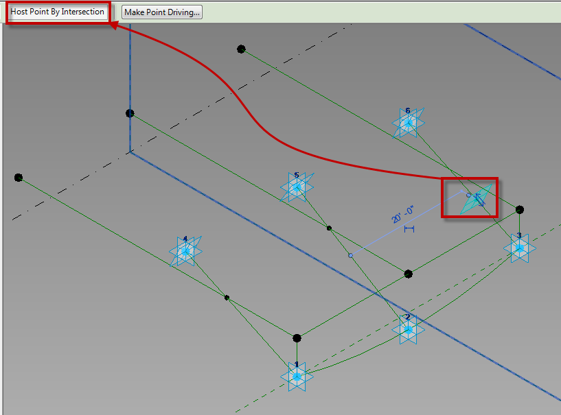
Move the adaptive points 4, 5 and 6 up vertically, then host points on the reference lines between the front and back adaptive points.  Select these new points and pick host by intersection, and select the reference lines above.

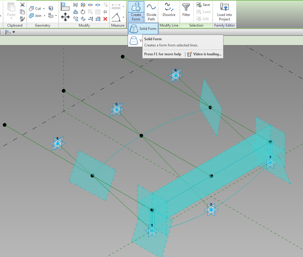
One those points are hosted by the intersections draw a spline through points from them. Then select the two spines, and three front reference planes and create a solid form from them.

Apply materials to the solid and it is ready to use.