Revit Basics – Selecting a Detail Bubble

For several reasons Revit users will often want to show only the bubble portion of a section cut or a callout.  For example, they want a bubble shown thus:
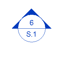
This is normally achieved via pulling the tail in very close.  Unfortunately, that part of the bubble is what one would click in order to select the section cut (since clicking on the bubble itself will not work).  There are a few ways to get around this, some more common than others.

First, one might draw selection/crossing window to select the bubble.  This will work, but might cause other objects to also become selected.

Second, using the omnipresent tab method to tab to the bubble will work.

Finally, perhaps the least known solution, holding down the control button will allow the bubble to be selected by clicking it.

This works with all veiw types including Levels, Sections and Callouts.

Changing Multiple Family Type Values

In a training session the question was asked how to change multiple parameter values in a family when there are several types already set up.  This is a tip I have been using for years and I know it has been posted many times but thought I would add my version to the topic.  The easiest way to do this is to add a value in the formula column, hit apply.  This will change the value to all types in the family, then delete the formula and you have updated all the types.

Revit Basics – Orient to View

This is an excerpt from an article that I wrote for AUGIWorld.

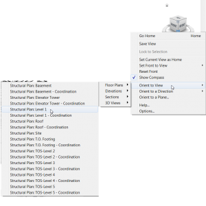
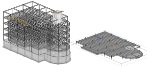
Models routinely become large or complex over the life of a project, and consequently a Revit user will occasionally want to isolate, in 3D, a certain area of the model or a particular group of elements.  The novice Revit user will then begin the tedious task of hiding elements to achieve the desired view.  Of course numerous options are available to quicken this process, such as toggling the visibility of different categories of elements, temporarily hiding/isolating elements in view, applying ghosted settings, manually adjusting section boxes, and perhaps even filters and/or worksets. This approach will eventually work; however, the task of isolating a particular section of a model can be quickly achieved by using the Orient to View command, which is found by right-clicking on the View Cube, shown in the first image.  The second image shows a floor that has been isolated via the Orient to View command.

The way this command works is to adjust the section box such that it mimics the view range and the crop region of the selected view.  To return to seeing the entire 3D model, either turn off the section box in the view properties, or manually stretch it back.

Revit Basics – Create Similar

This is an excerpt from an article that I wrote for AUGIWorld.

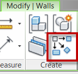
Until Revit 2010, the only easily accessible location to activate the Create Similar command was in the right-click context menu after a single element is selected. Revit beginners probably didn’t even know the command existed.  Create Similar is now available on the Modify Tab, but remains grayed out until a single element is selected.  The inquisitive Revit novice may have discovered this command’s function by hovering over it and reading the tooltip, but others may not have noticed it and don’t know it exists.

The Create Similar command activates whatever command is necessary to create a new instance to match the type of an existing element.  For example, selecting a wall and clicking Create Similar activates the wall command and sets the type of the wall to match the one selected;then the user maydraw another wall instance.  This command is particularly useful for several reasons.  It matches an element’s type without the user having to know that type, and without having to navigate through the (occasionally long) Type Selector looking for something specific.  One may just copy elements to achieve a similar outcome, but then the user is left modifying, moving and altering the new instance after it is placed.  Also note that copying will not only copy the desired element, but also any hosted elements, i.e, copying a wall will also copy all of the doors and windows in that wall.  While extremely useful, the Create Similar command is not without its flaws.  It only matches type properties, not instance properties – or at least not all instance properties – so, for example, it will create a wall of the same type, but not of the same height.  Strangely, however, it will match location line settings, which is an instance property.

Adaptive slab edge

While training a client today the question had come up of how do you do a slab edge when the slab isn’t flat?  This can always be done as an inplace family sweep with a defined profile, but as we all know to many in-place families have a tendency to slow Revit down.  So we went through the process of creating an adaptive family.  The only complaint I have is the limited categories that adaptive components can be, so in this case we left it as a generic model so that it can host rebar.

Start with the Generic Model Adaptive  template, then change the category if desired, we left ours as a generic model. 

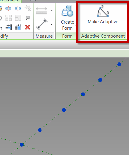
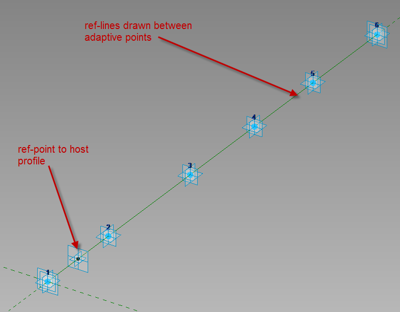
Place ref-points as needed in the view, select the ref-points and change them to adaptive in the contextual ribbon.

Draw ref lines from the first adaptive point to the second to the third etc., make sure 3D Snapping is on before drawing.  Next draw one ref-point on the ref-line, this point will be used to host the profile.

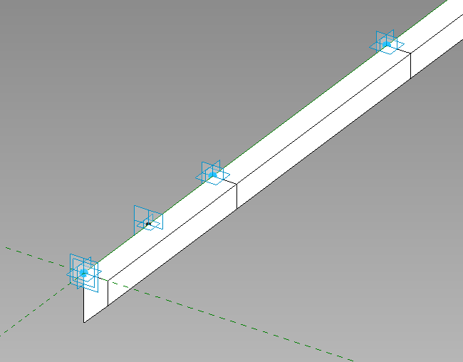
Since profile families can’t be used inside of an adaptive family create a generic model using model lines to be the profile of the thickened slab, load that into the family and place it on the ref-point.  Select the profile family and map the parameters to parameters in the adaptive family.  Select the profile and the ref-lines then create form.

This is what we had come up with instead of in-place families.  Comment if this works for you or not.