Random Clicks Windows Scroll Bars

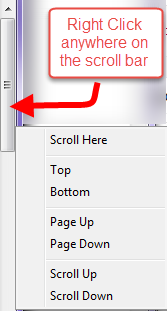
A while back I had accidentally right clicked on a scroll bar, and I noticed a dialog box come up that I had never seen before.  It allows for ANY windows scroll bar to be moved to the top, bottom, current location etc..  This is a small little tip that I use a lot when I have scrolled to the bottom and want to get back to the top, especially in the Project Browser for Revit.

Windows_Scroll_Bar


Adaptive Component Water Volume

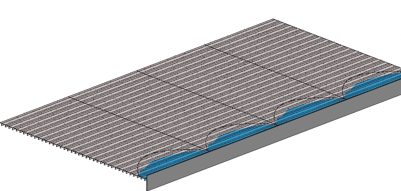
Dezi was working on a project where she had to figure out the amount of water that was accumulating in a failing double T.  Of course she approached the problem as an engineer and incorporated a lot of math into the family.  I decided that was something best left to an engineer and I decided to take advantage of that intelligence she had incorporated into the double T family and create an adaptive component to display the water graphically as well as extract volume from the family.  It is hard to see in the picture but all of the double T’s are sagging and the adaptive “Water Volume” family is reacting to the as well as the depth of water.
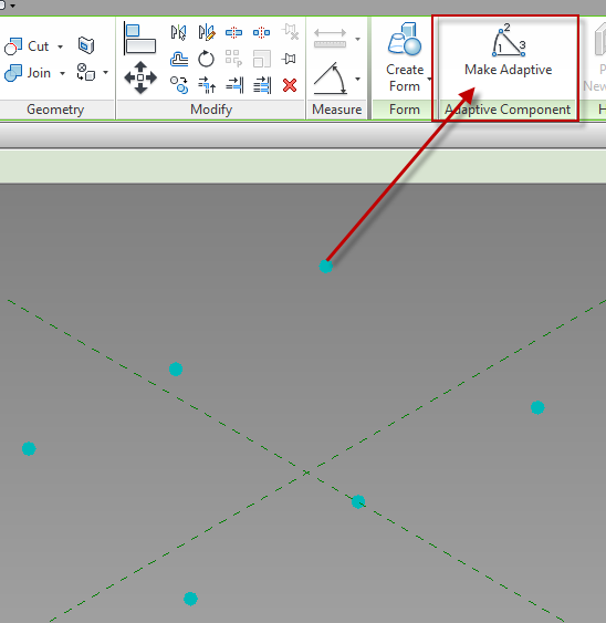
I started with a Generic Model Adaptive for this task.  This family was going to be controlled by the ends and middle of 2 separate double T’s. I placed 6 reference points on the level.  Once those are placed select them and change them to adaptive points.
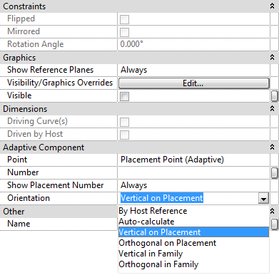
Once the points are made Adaptive new properties will be available.  Orientation is a key value to pay attention to, in this case the points need to be changed to Vertical on Placement.  If this is not selected then the form will be allowed to go any direction, we want this form to always be vertical.
The second step was to host a reference point onto point 1 & 3. It is critical that the “Z” work plane for each point be set before the point to be hosted on it is placed.  To do this use the Set Work Plane button then select the appropriate plane on the point.
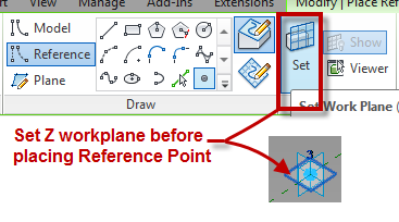
Once those points were created I mapped a parameter (Water Depth) to the offset value of the points.
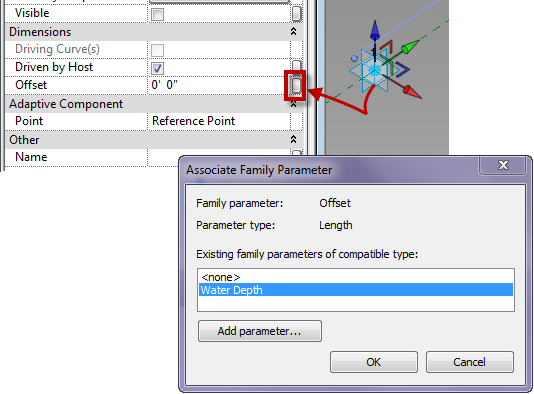
Next I associated a point to each of those points on their vertical work plane, clicking ok to the warning dialog.
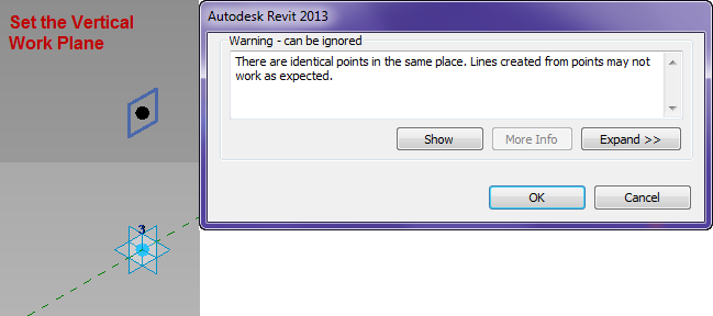
I then mapped a parameter to the offset of those points. so that they will go back towards the other points.  Next draw a reference line between the points hosted on adaptive 1&3, then place a reference point at the midpoint on the reference line.
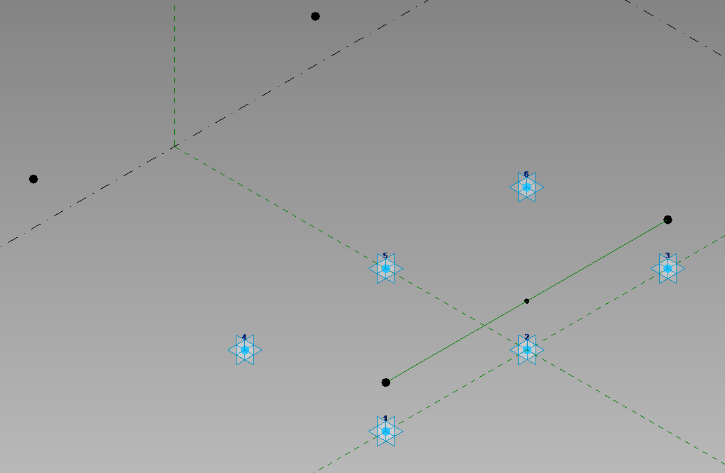
Host another point on the point hosted on the center of the reference line and associate a parameter to the offset value of this point.  Then connect the points with Reference Lines (as per the image below), making sure 3D snapping is turned on.  Draw a spline through points use the adaptive points 1,2 and 3.
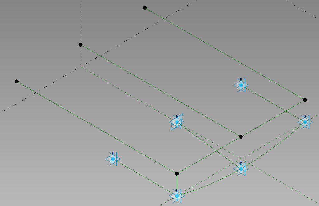
Move the adaptive points 4, 5 and 6 up vertically, then host points on the reference lines between the front and back adaptive points.  Select these new points and pick host by intersection, and select the reference lines above.
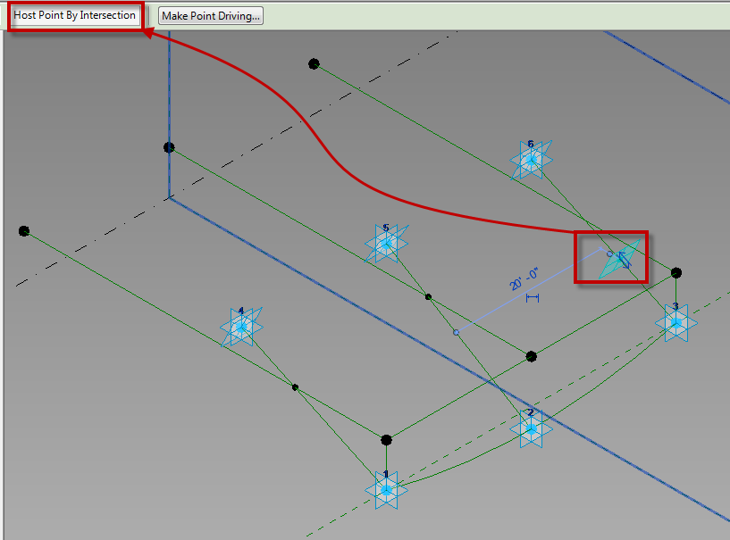
One those points are hosted by the intersections draw a spline through points from them. Then select the two spines, and three front reference planes and create a solid form from them.
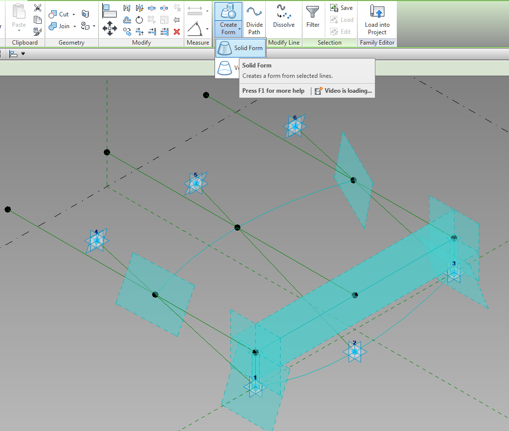
Apply materials to the solid and it is ready to use.

 

Dimensioning Sloped Framing

I have had some questions come up about dimensioning sloped framing, so I thought it deserved a blog post.

Question: Why can’t I dimension to framing members when they are associated to a sloped work plane?

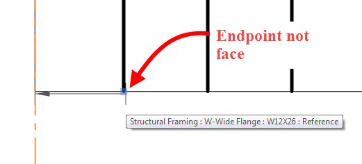
  • This question comes up when attempting to dimension in plan, in a coarse level of detail, when the framing member is Normal to the work plane, and when using the Linear Dimension option.  Beams can be selected using the linear option, however the user won’t be selecting a face, since it isn’t perpendicular to the view, they will be selecting the end point of the graphic line.
  • Make sure when dimensioning the endpoint of the beam is being selected and not a face.  It is sometimes hard to see but a grip will come up, along with a tool tip, when the end of the beam is selected.

SlopedFramingEndpoint


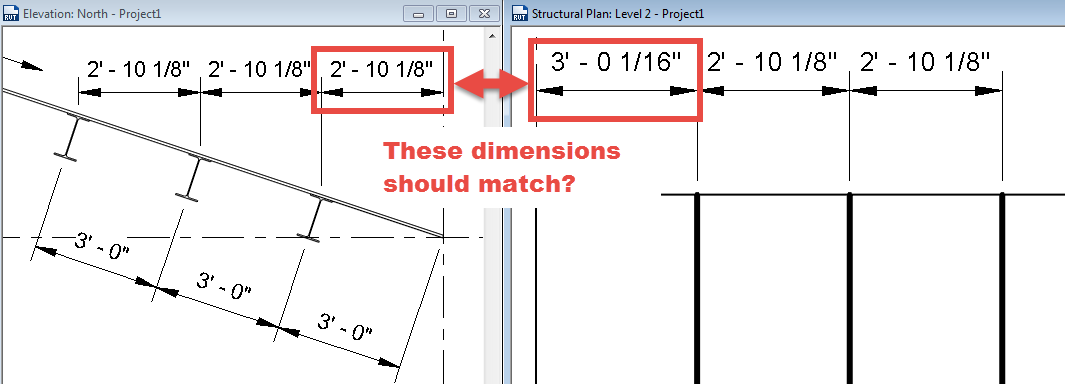
Question: Why aren’t my dimensions equal in plan and section?

SlopedFramingDimensions

  • This issue is due to the location of the symbolic line of the framing member.  In the elevation above the beam was dimensioned to the Top Midline, however the default setting for “Stick Symbol Location” is set to “Center of Geometry”, thus making the stick symbol location in plan different then in elevation.  Depending on how the family is created this property may only affect the plan and not any of the other views.
  • Selecting the framing member and changing the “Stick Symbol Location” value to “Top of Geometry” will insure that the plan dimension is the same as the elevation dimension.  However, it will need to be changed for all of the elements being dimensioned.

SlopedFramingFixed


I hope this helps clear up these two common questions.  If anyone has other tips about these please comment.


Synchronize Now vs Synchronize and Modify

I thought I would write this post to clarify the difference between the two options for Synchronizing a Revit file since I often see users not understanding the difference between the two.  I see this issue come up often when a user publishes coordinates to a linked file they now own part of the Project Standard Worksets and the Synch Now will not give up the rights.


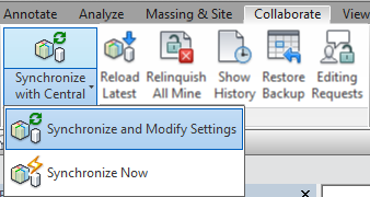
When going to the synchronize drop down you may notice there are two options, Synchronize and Modify Settings and Synchronize Now.  A lot of users like to use the Synchronize Now button because it is a single click operation without the pop up of another dialog box.  This is not recommended practice.  This button does not allow a user to change what worksets and/or elements they are relinquishing their rights to.  This becomes an issue when a user edits a family, changes project standards, creates a new workset etc.  thus not allowing team member to work on elements that have not be relinquished.


Synch

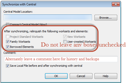
The preferred method is to use the Synchronize and Modify Settings.  This option will allow the user to make sure they are giving up all rights by selecting any and all checkboxes available when the dialog box opens.  Alternately comments can be added such that these can be seen when looking at the history of the file or when trying to recover backups.

Synch_Settings

If there is something that needs to be locked down that is on a workset then unchecking the checkboxes will keep those locked to the users who has them checked out.


Revit Structural Deck Line Types

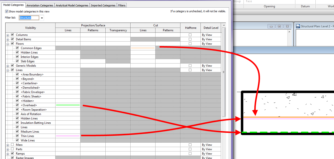
For a few releases now Revit has had the capability to model composite decks with 2D graphics to display the metal deck when in sections.  While working with a client the question came up on what determines the line weights / line types in views.  After some trial and error I was able to determine what is happening with these lines.  When the section is perpendicular the deck, nothing special the line weights are simply controlled by the Floor category and the Section styles, however it is a different story when cutting parallel to the deck.

The line that shows the transition from the layer above to the metal deck (shown orange below) is the subcategory Common Edges under Floors

The line that is representing the underside of the top of the metal deck (shown magenta below) uses the subcategory Thin Lines under the Lines category

The line that represents the top of the lower portion of the metal deck (shown green below) uses the subcategory Overhead under the Lines category

Composite_Deck_LineStyles