Tag Archives: Adaptive components

Adaptive Component – Everyday Uses part 1

This past year was a good one and I had the privilege to speak at several conferences and one of the most popular topics was adaptive components (my sessions were titled Everyday Uses of Adaptive Components). I thought I should share some of the process and families that I had presented.  This is going to be a series of posts discussing the process of adaptive components, their advantages and pitfalls as well as a tutorial on how to create a few.

Family Template Types

When starting an adaptive family, the first step is to understand what templates are available and decide which template is the most appropriate for the task at hand.  There are three templates that provide a starting place for an adaptive family: Curtain Panel Pattern Based.rft, Generic Model Adaptive.rft, and Generic Model Pattern Based.rft.  Even though the curtain panel pattern based family sounds like it can only be used on a divided surface of a mass, etc, it can actually be used similarly to a normal adaptive family.  Additionally, starting from the Curtain Panel Pattern Based template, and then changing the category to generic model would produce the same result as starting with the generic model pattern based family.

Generic Model Pattern Based / Curtain Panel Pattern Based

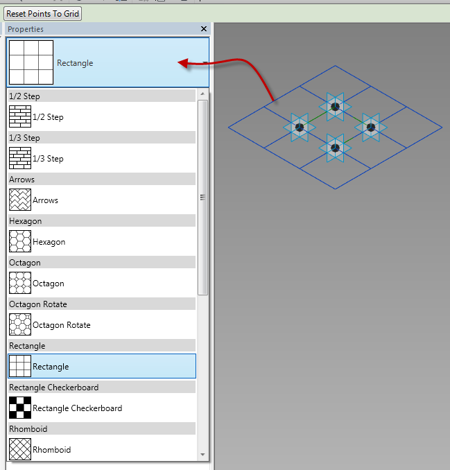
When starting with one of the pattern passed templates, there is a grid system (tile pattern), along with 4 points on that system, and reference lines connecting those points.  Unlike many family templates, these points, grids and lines are not static and can be adjusted.  To change the tile pattern and the amount of adaptive points, select the grid system (must be done by selecting the outside of the grid), and in the type selector, change the grid tile pattern type.  Depending on which tile pattern is chosen, the quantity of adaptive points may adjust along with the grid system.

TilePattern_TypeSelector

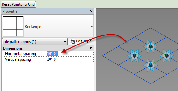
Note: To flex the family select the grid system and change the spacing in the instance properties

TilePattern_Properties

This type of template is ideal for creating a shape or panel that needs a specific quantity of points.  The downside to using this template type is that additional adaptive points can’t be added, the adaptive points can’t be re-ordered, and there can never be shape handle points in the family.

Generic Model Adaptive

This template is the most flexible type, but it also starts from basically a blank slate – only a couple of reference planes.  This means everything has to be created from scratch, starting with adding adaptive points and reference lines. This template type does allow for an infinite amount of adaptive points, as well as the flexibility to re-order the adaptive points at will and to add shape handle points.  This template type will allow for levels to be generated, but the levels DO NOT transfer to the project or massing environment; basically they simply act as horizontal reference planes.

GenericModelAdaptive

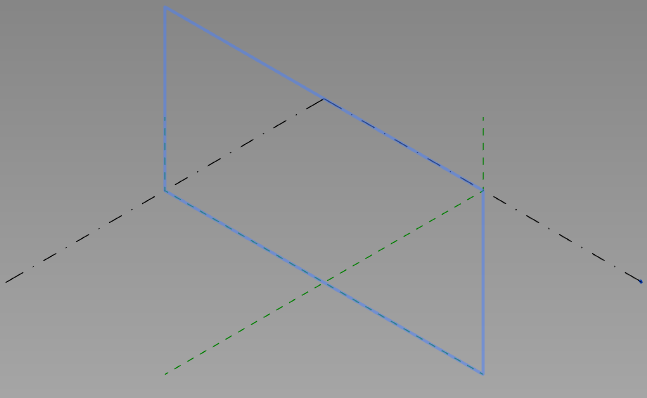
Note:  The Generic Model Adaptive looks extremely similar to the massing template, however adaptive points can’t be created in the massing environment.


Up next Adaptive Component – Everyday Uses Part 2

Adaptive Component Water Volume

Dezi was working on a project where she had to figure out the amount of water that was accumulating in a failing double T.  Of course she approached the problem as an engineer and incorporated a lot of math into the family.  I decided that was something best left to an engineer and I decided to take advantage of that intelligence she had incorporated into the double T family and create an adaptive component to display the water graphically as well as extract volume from the family.  It is hard to see in the picture but all of the double T’s are sagging and the adaptive “Water Volume” family is reacting to the as well as the depth of water.

I started with a Generic Model Adaptive for this task.  This family was going to be controlled by the ends and middle of 2 separate double T’s. I placed 6 reference points on the level.  Once those are placed select them and change them to adaptive points.

Once the points are made Adaptive new properties will be available.  Orientation is a key value to pay attention to, in this case the points need to be changed to Vertical on Placement.  If this is not selected then the form will be allowed to go any direction, we want this form to always be vertical.

The second step was to host a reference point onto point 1 & 3. It is critical that the “Z” work plane for each point be set before the point to be hosted on it is placed.  To do this use the Set Work Plane button then select the appropriate plane on the point.

Once those points were created I mapped a parameter (Water Depth) to the offset value of the points.

Next I associated a point to each of those points on their vertical work plane, clicking ok to the warning dialog.

I then mapped a parameter to the offset of those points. so that they will go back towards the other points.  Next draw a reference line between the points hosted on adaptive 1&3, then place a reference point at the midpoint on the reference line.

Host another point on the point hosted on the center of the reference line and associate a parameter to the offset value of this point.  Then connect the points with Reference Lines (as per the image below), making sure 3D snapping is turned on.  Draw a spline through points use the adaptive points 1,2 and 3.

Move the adaptive points 4, 5 and 6 up vertically, then host points on the reference lines between the front and back adaptive points.  Select these new points and pick host by intersection, and select the reference lines above.

One those points are hosted by the intersections draw a spline through points from them. Then select the two spines, and three front reference planes and create a solid form from them.

Apply materials to the solid and it is ready to use.


2013 Divided Path Command

I was working on a layout of a panelized system around a tower, and I was using the new Divided Path commannd.  I found it has a limitation of 200 divisions. At first I thought this was going to be an issue but it made me rethink the shape and I ended up with a better solution anyway.  Just a heads up for everyone trying to use the command.

Adaptive slab edge

While training a client today the question had come up of how do you do a slab edge when the slab isn’t flat?  This can always be done as an inplace family sweep with a defined profile, but as we all know to many in-place families have a tendency to slow Revit down.  So we went through the process of creating an adaptive family.  The only complaint I have is the limited categories that adaptive components can be, so in this case we left it as a generic model so that it can host rebar.

Start with the Generic Model Adaptive  template, then change the category if desired, we left ours as a generic model. 

Place ref-points as needed in the view, select the ref-points and change them to adaptive in the contextual ribbon.

Draw ref lines from the first adaptive point to the second to the third etc., make sure 3D Snapping is on before drawing.  Next draw one ref-point on the ref-line, this point will be used to host the profile.

Since profile families can’t be used inside of an adaptive family create a generic model using model lines to be the profile of the thickened slab, load that into the family and place it on the ref-point.  Select the profile family and map the parameters to parameters in the adaptive family.  Select the profile and the ref-lines then create form.

This is what we had come up with instead of in-place families.  Comment if this works for you or not.


Space Frame Panel by Pattern

In a previous post I added a curtain panel by pattern to a mass family, this family was set up to be a space frame.

In this post I will get into how this family was created by using the curtain panel pattern based (CPPB) family template.  With any CPPB family it is crucial to pay attention to the workplanes that are being used, most of the times these will either be points or reference lines.  My first few attempts at CPPB families I didn’t pay as much attention as I should have and struggled getting the results that were needed, by paying attention to that little detail would have saved a ton of headaches.

When a CPPB family is open there will be some default ref lines and adaptive points, depending on what the tile pattern grid is set to will determine how many of each there are.  By default it starts with Rectangle, if a different pattern is needed then select the perimeter of the blue grid on the screen and change it in the type selector.

In the space frame family Rectangle is what I needed, so no changes were necessary.  The first thing that was required with this family were some reference points.  These reference points need to be related to the Adaptive points, to do this the workplane of each adaptive point must be selected before placing the ref points.

Once the workplane is set place the ref point directly ontop of the adaptive point, do this for all four corners, or adaptive points.  One that is done select the ref points that have been placed (filter is a great tool for this) and  add a parameter for the offset property.

The end result should look like this…

The next step was to draw a reference line from point to point.  The critical step in this is to make sure the 3D snapping is turned on while selecting the the reference points.

Next draw another ref line between the two new ref points.  Again making sure that 3D snapping is turned on.  Add another ref point to the middle of this line.  Draw 4 new ref planes from the corners to this ref point. 

Now that the rig is done m1ake sure to flex it, move the adaptive points up and down, also select the tile pattern grid and change the properties of the horizontal and vertical spacing.  At this point in time this rig could be applied to a mass, although nothing will be displayed since only reference objects have been used. 

Now sweeps will be needed to represent the frame itself, this can be done in many different ways, this post is just going to use model lines swept along the ref-planes. To do this I will keep making one of the ref-points my workplane then draw a circle on that plane (paramatize as needed), select the circle and the appropriate ref-planes, then select create form.

 Note:  When a sweep follows only a single path, and there are parameters assigned to the shape, the shape can vary along the path.  For these instances select the sweep and select the Lock Profile button.

Please post any questions or comments if you have any.