Tag Archives: Tips

Revit 2016 r2 reference planes follow up

In one of the forums a user had suggested that Autodesk set the default value to newly placed reference planes “Is Reference” value be set to “Not a Reference” instead of weak reference.  This has been possible to set up for a while now.  If you create your own family templates then make sure to start to draw a reference plane, but before clicking on screen set the “Is Reference” value to “Not a Reference” then draw a reference plane, and delete it.  Now save the family and rename in windows explorer to .rft.  This feature doesn’t however work on everything, it will still be a “Weak Reference” when copied or mirrored.

So yes I agree it would be nice if Autodesk would make the default setting to be “Not a Reference” when reference planes are created no matter if drawn, copied, mirrored or whatever.

Revit 2016 R2 reference planes

Currently I have been working on family editor training as well as creating content.  With the 2016 R2 update of the minor feature updates are the changes to reference planes inside the family editor.  The first and most noticeable update is the fact that the referenced plane when selected displays <click to name> on both ends of the reference plane.  Two things are new here, first you can select to rename, we no longer are forced to go into the properties to edit the name, second the name is displayed at both ends of the reference plane.

A subtle improvement that may go unnoticed is the fact the name displays differently depending on which view the reference plane has been drawn in.  For example if the reference plane in drawn in plan then the name will be parallel to reference plane in plan, if it had been drawn in an elevation then the name will be perpendicular to plane in plan.  Plus the names will be displayed on the back (or negative value) side of the reference plane depending on the direction they were drawn.

2016 R2 Reference Planes

Adaptive Component – Everyday Uses part 5 Roof Cricket

Continued from..

Adaptive Component – Everyday Uses part 4
Adaptive Component – Everyday Uses Part 3
Adaptive Component – Everyday Uses part 2
Adaptive Component – Everyday Uses part 1

Roof Cricket Family

This section of the handout will give step by step instructions to create a variation on the roof cricket family.

  1. Start with the OOTB GenericModelPatternBased template
  2. Draw a point directly on top of adaptive point 2, making sure the Z work plane is used as the workplane
    • Start the Reference Point command
    • Use the Set Work Plane command
    • Tab to get the horizontal work plane on point
    •  Roof_Cricket_Rig_01
  3. Select the recently placed point
    • In properties change the “Offset” value
    • Select the “Associate Family Parameter” button
    • Create a new parameter named “Rise”, and make it instance based
    •  Roof_Cricket_Rig_02
  4. Draw a reference line between the newly created point and adaptive point 4, making sure the Draw on Face selection is highlighted and 3D is checked in the options bar
    • Roof_Cricket_Rig_03
  5. Draw a reference line from adaptive point 1 to the new reference point
  6. Draw a reference line from adaptive point 3 to the new reference point
  7. Draw a reference line from adaptive point 2 to 4
  8. Set the work plane to be the horizontal plane of the diagonal reference line
  9. Place a dimension from adaptive point 2 to 4 (make sure adaptive points are being selected)
  10. Label the dimension with a new reporting parameter and call it “Run”
    • Roof_Cricket_Rig_04
  11. Open the Family Types dialog
  12. Create a new instance based length parameter, label it “Slope”
  13. Add the formula “(Slope*Run)/1”
    • Roof_Cricket_Rig_05
  14. Select three of the upper reference lines
    • Select the create form button
    • Select the surface option
    • Repeat for the other three upper reference lines
    • Roof_Cricket_Rig_06
  15. If desired, add a material parameter to the surfaces
  16. Save the file


Adaptive Component – Everyday Uses part 4

Continued from..

Adaptive Component – Everyday Uses part 3
Adaptive Component – Everyday Uses part 2
Adaptive Component – Everyday Uses part 1
 

Nesting Families

When creating families it is sometimes necessary to nest other families, and this is more common with adaptive families.  However, not all family types can be used with adaptive families. For example profiles, structural columns, or beams cannot be loaded into an adaptive family.  If a nested profile is needed, then a generic model family with model lines, either adaptive or not, can be used in lieu of a profile family.

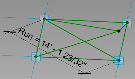
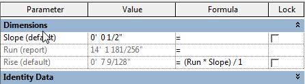
A great family to consider nesting, especially when adaptive families are a new to the user, is the out-of-the-box “Diagnostic Tripod” family.  This family will display how the adaptive family is working once it is loaded into another family or project.

Repeaters and Divisions

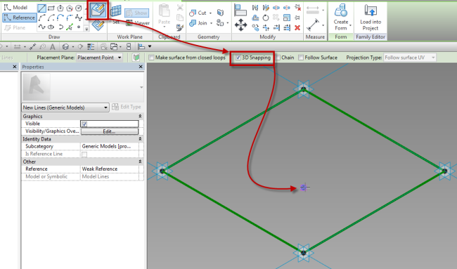
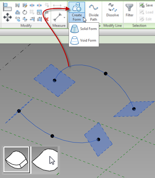
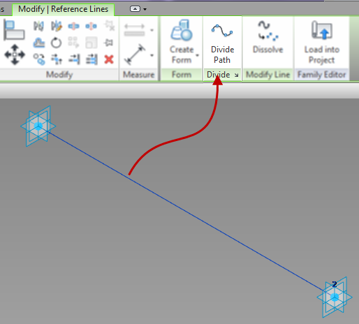
If a family is going to be repeated, which is similar to an array, then nesting families is a must, as is using a divided path or surface.  The first step is to create a division from either a surface or a line.  To do this, select the element and use the Divide Path or Divide Surface command.  Since the 2013 products, a series of lines may be selected and divided as a single element.

DividePath

A divided path also has properties that will allow for a beginning or end indent.  These properties give further adjustment to the location of the hosted elements.

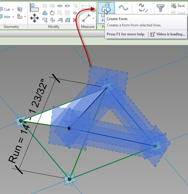
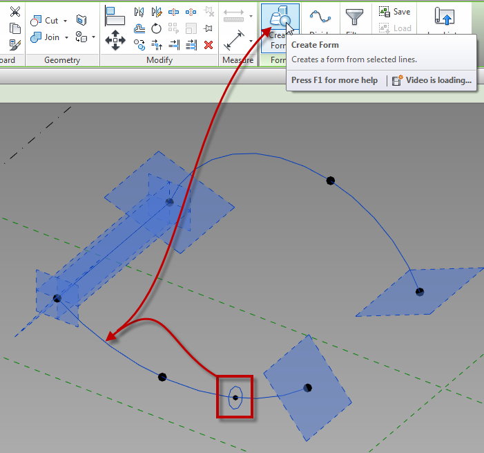
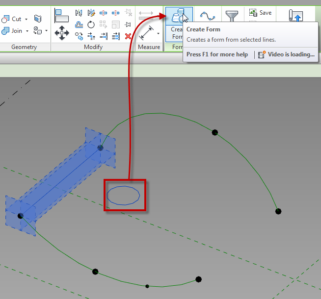
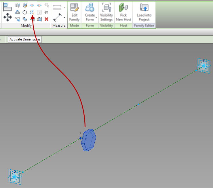
If a nested family will become a repeater, it will have to be an adaptive family.  To create this, first place the family on a point, or series of points, that was created from the division tool.  When doing this, make sure to select the node that was created by the division.  Next select the element and use the Repeat command (same button as array in a normal family or project).

Bolts_Repeat

Up next…

Adaptive Component – Everyday Uses part 5

Adaptive Component – Everyday Uses part 3

Continued from..

Adaptive Component – Everyday Uses part 2
Adaptive Component – Everyday Uses part 1

Creating Forms

Unlike the normal family editor, in adaptive and mass families, surfaces and solids can be created.  These are created using the Create Form button and not extrusions, sweeps, etc..  Unfortunately points cannot be used to create elements, reference lines and/or model lines must be used for this task.  Lines can be used if they are part of the rig, however, if additional lines are required, then they need to be created prior to creating solids or surfaces.  In the adaptive (as well as mass) family environment, surfaces can be created from a single line or from multiple lines.

Surfaces and Extrusions

To create a solid or surface, select the desired lines and select the Create Form button.  Voids can be created in the same manner.  If Revit can determine more than one way to create a solid, or if it can create a surface, different images will appear on the screen allowing a user to select the appropriate one.

CreateForm

Sweeps

A sweep is created by drawing lines for the shape of the sweep, then by selecting those and the lines that represent the path.  Once all of the elements are selected, use the create form button to create the sweep.

CreateForm_Sweep

Revolves

A Revolve is created by selecting a group of lines or arcs that are all parallel to a single line.  This one line acts as an axis.

CreateForm_Revolve

Once surfaces or solids have been created, their faces and edges can be used to generate additional forms.  For example, the edges of a cube can then be used for the path of a sweep, or the edge of a surface can be used to generate an additional surface.

Up next…

Adaptive Component – Everyday Uses part 4