Tag Archives: Tips

Align Eaves

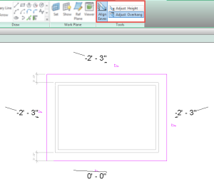
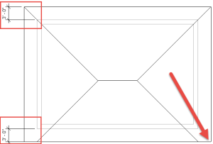
During a recent session of Revit Radio I was asked a few questions about roofs and their properties.  A post I did a while ago on Roof Overhang Values which covered one of the questions.  However it didn’t answer the question of why are the roof eaves not aligning? In the image below both sides of the roof have a 3′ (914mm) overhang with the same roof pitch on the entire roof.

Align Eve Plan

The reason this may happen is the fact that one of the sketch lines used the pick wall tool whilst the other was simply drawn as a line (or possibly the pick lines tool with an offset).

What the help file doesn’t explain is that when the pick walls tool is used along with defining that edge as a slope then the slope starts from an edge of the wall picked (the edge of the wall depends on if Extend into Core is used or the roof is set as a Truss or Rafter).  If a line is sketched then the slope will start from sketch line itself.  Using both of these tools will cause the issue as seen in the above image.  Revit however does have a simple tool to assist in adjusting the roof eaves if this situation does arrive.  The tool to accomplish this task is Align Eaves and can only be accessed while in sketch mode.

Align Eaves

If the eaves are aligned Revit will flag a warning of “All eaves are already aligned”, if the eaves do not align then Revit will display the elevation of the eaves relative to the closest level.  There are also two overlooked option on the contextual ribbon “Adjust Overhang” & “Adjust Height”.  Before attempting to adjust the eaves make sure to select the correct option, most of the time this will be Adjust Height, yet the default is Adjust Overhang.  Once the correction option is selected choose the value that is correct and select the sketch lines that need to adjust, similar to the align tool.

Foundation Walls – Wall Function

During a session of Revit Radio this month the question came up  “Why can I only model Foundation walls with the depth value?”  Of course I couldn’t answer this question with a simple answer, I went in-depth into the parameter “Function”.

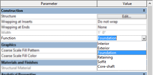
When the type properties of a wall is selected there is a property of “Function”, according to the help file this:

Categorizes the wall as Exterior, Interior, Retaining, Foundation, Soffit, or Core-shaft. Function is used in scheduling and to create filters that simplify a model for visibility or when exporting.

Wall Function

Yes these values can be used to generate filters to turn off wall of a given function, however what the help file fails to inform us is that these values also have other built in information associated to them.  The most obvious, or not so obvious due to the above question, is that if Foundation is selected as a property then this will disable the capability to model the wall with “Height” or “Depth” option and will be forced to “Depth”.  Hence only allow walls with this property to be modeled going down.  However the little known rule is that Revit will also remember settings that were used for the previous wall of the same function.  For instance if a wall who’s function is set to “Soffit” and it was modeled with a base offset of 8′ (2440mm) and then a wall who’s function is set to “Interior” will not be modeled with the same base offset but will use the previous “Interior” walls settings.  Usually when I am setting up templates for clients I pay close attention to these setting and keep things consistent within wall types.  The last template any wall with gypsum board on a single side was set to “Soffit”.

On a side note Doors, Floors, Stairs amongst other families also have the same “Function” parameter, however these only have the options for “Interior” and “Exterior” and really are there for generating filters.  I have submitted to Autodesk that more categories have these features such as Windows and Railings.  If the help file is true and I want to create a filter for “Interior” or “Exterior” then it would be nice to have it associated to all objects that could be in either location.

Parameters for Sheet List

As many users know in Revit if there are multiple disciplines working in different models things can be scheduled from those linked models, sheets are no exception.  However most companies will have custom parameters to get the schedule to sort, group and filter a give way.  So I am asked a lot how can the consultant easily get this information?

The common answer I hear is to Transfer Project Information which will bring along the necessary project parameters needed to fill out for the prime to get their schedule set up accordingly.  The problem with this feature is that it will bring along all of the project parameters, most of which will not mean anything to a team outside the prime office.

My suggestion is to open the model of the project lead and find the schedule that is being utilized.  Simply Copy that schedule to the clipboard and paste it into your project.  This will bring only the project parameters utilized for the sheet index and leave all the unneeded values behind.

My personal favorite is an option where the project lead creates a blank project that only has the project parameters and has the appropriate schedule inside of it, along with instructions on how to use all of the values that are needed for the sheet index.  This way the consultants can use Transfer Project Information easily and only get what is needed and have a direction on how to utilize them.


Revit 2016 Room Improvements

In Revit 2016 (both R2 and prior) there has been a subtle improvement to the display of room while in a section view.  With a room selected in a section view Revit will display the values for both the Upper Limit Offset as well as the Base Offset for that given room.  It will also display the Computation Height for the level associated to the room.  Small changes like this stream line our workflows allowing us to visualize values with out looking at the properties dialog.

2016 Room Selection Section

Revit 2016 r2 reference planes follow up

In one of the forums a user had suggested that Autodesk set the default value to newly placed reference planes “Is Reference” value be set to “Not a Reference” instead of weak reference.  This has been possible to set up for a while now.  If you create your own family templates then make sure to start to draw a reference plane, but before clicking on screen set the “Is Reference” value to “Not a Reference” then draw a reference plane, and delete it.  Now save the family and rename in windows explorer to .rft.  This feature doesn’t however work on everything, it will still be a “Weak Reference” when copied or mirrored.

So yes I agree it would be nice if Autodesk would make the default setting to be “Not a Reference” when reference planes are created no matter if drawn, copied, mirrored or whatever.