Tag Archives: Tips

Revit Basics – Tab

This is an excerpt from an article that I wrote for AUGIWorld.

“Press tab” is likely one of the phrases beginner Reviteers get tired of hearing.  It is common knowledge that the tab button can be used to cycle through elements to enable the selection of a specific element in a congested area.  What is lesser known, or at least lesser-used, is that pressing shift + tab will cycle through the elements in the opposite direction.  Knowing this small item would prevent this very familiar occurrence: “Tab, tab, tab, tab, tab, shoot! I skipped the element I wanted….tab, tab, tab, tab….”

Just in case it has not been said enough, the following is a list of some of the useful applications for the tab button: cycle through elements in a congested area; instead of just one segment, select a chain of walls or lines; select only a segment of chain of walls (select the first one and then press tab while hovering over the last desired segment); instead of one at a time, select connected beams all at once; cycle through snap locations (end point, intersection, etc.); get to objects in a linked file to see the properties.

Revit Basics – The Spacebar

This is an excerpt from an article that I wrote for AUGIWorld.

In my article I called this section “The Magical Spacebar”. No, inserting spaces between words in text is not the magical function of the spacebar.  When inserting a component, new users tend to place the component somewhere in their workspace and then will alter said component to their liking.  These alterations often include rotating the element.  What the beginner doesn’t know – and often takes a long time to learn – is that hitting the spacebar before placing the component will rotate it.  Furthermore, if hovering over another element in the view, the spacebar will cause the component to orient to the same direction. Pressing the spacebar again will then rotate the component 90 degrees from that direction.  Finally, if hovering over an intersection, the element will only rotate 45 degrees instead of 90.
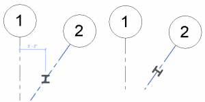
In addition to rotating a component prior to placement, the spacebar can also be used to rotate or to flip elements (or multiple elements) that are already placed.  Using the spacebar to rotate after placing a component can be a little troublesome because the base of the rotation is the insertion point of the component, so rotating in this manner may require more moving and aligning.  The flipping works with any element that has a flip control (the two little blue arrows that appear when an element is selected).  For example, select a wall, or several walls, and use the spacebar to toggle the walls interior/exterior sides.

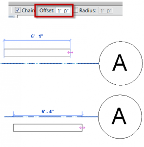
Another application of the spacebar is to use it in conjunction with elements that use the offset option.  While sketching an element with an offset option, the spacebar will toggle the direction of the offset.
Finally, when doing anything – from drawing a line to changing a dimension – the spacebar can also be used in place of the feet and inches symbol.  So, instead of typing 5’4”, for example, simply type 5 4 and the result will be the same.  Using the dash key also works in the same manner as the space bar (5-4), which is useful because the dash is one of the keys on the number pad.  Please note, however, that the dash approach only works between feet and inches; a space is still required between whole and fractional inches, i.e. 5-4 ½ works, but 5-4-1/2 does not.

Linework Tool and Underlay

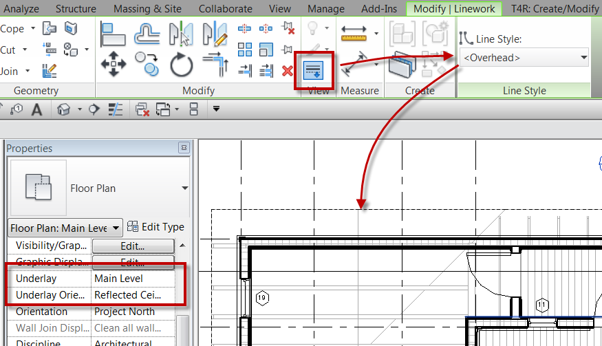
This is a tip that I have been showing for years and I was reminded of it today while training a student.  The tip involves the use of the Linework tool along with underlay while in plan views.  This student was asking how to display the roof overhang in plan and wondered if it could be displayed as hidden lines.  The first, most CAD-like, response was to simply draw hidden lines where these elements were.   I explained how that is an option, but what happens when the roof changes or moves?  Now someone would have to go back and adjust the lines to match the changes.  If Revit could do that automatically, that would be a better solution.  My suggestion was to turn on the underlay so that the elements in question could be seen.

To do this, set the underlay to the current level, and the set the plan orientation to Reflected Ceiling Plan.  Then, on the Modify tab in the View panel, select the Linework command and set the line style to <Overhead>.  Now select the lines that need to be displayed in the plan.  Once that is done go back and change the Underlay to None and the lines that had been changed via the Linework tool will still be displayed.


If you decide later that the lines are no longer needed DO NOT DELETE the lines, this will delete the physical element.  Instead, again use the Linework took and with the linestyle <By Category> and select the lines.  The lines will go back to their default display, or not displayed if the were changed as an underlay.


Continuous Overhanging Gable Roof

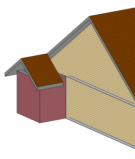
A question came up in the Linkd In Group for Club Revit  about creating a single roof with a gable end that would basically go underneath itself to attach back to a wall.  I thought I would do a post to my simple response, so that I can get a bit more detailed in the explanation.

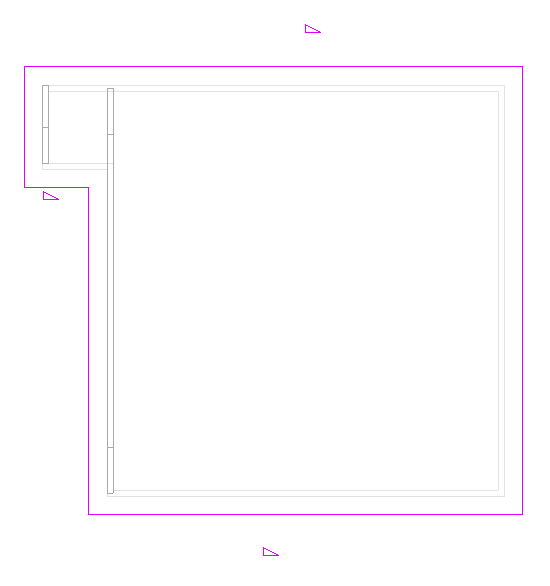
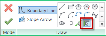
The first step is to create a roof by footprint, personally I would use the Pick Walls tool for this situation.  Uncheck the defines slope option to get the gable ends as needed.  Finish the roof when done


This doesn’t alone dosen’t get the small gable end roof to come back under itself to attach to the wall.  It also doesn’t automatically take the walls up to the roof.


I chose to model another wall above the other and make it the full length of the roof, and then attach that wall to the roof.  This way I have something to Join the roof to.


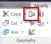
The next step is to use the Roof Join/Unjoin command located on the Geometry panel of the Modify Tab on the ribbon.


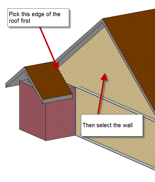
Pick on the edge of the roof that needs to Join to the wall and then pick on the wall.


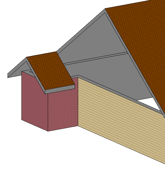
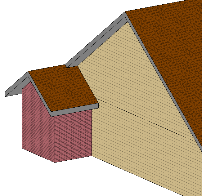
This will be the completed result.  Now just go in and add all the detail like soffits, fascias and gutters.


Show Walls Below Roof

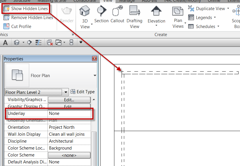
After my post about show hidden lines someone had contacted me and had a concern that this tool didn’t work for what he needed.  In this particular case the person was talking about showing walls below the roof.  He had went through and used the show hidden lines tool and some of the walls displayed hidden while other didn’t.  The underlay value had been set to display the floor below the roof, some of the walls remained half-toned and others displayed hidden. Once the underlay was turned off (see note below on underlay) the walls that weren’t showing hidden disappeared.  In this case there were actually different issues that were causing the walls not to display hidden.  One of the issues was with the view range settings.  The view range bottom and depth were set to to current level at 0″ so that nothing below the view could be seen, so once the underlay was removed the hidden lines didn’t display.   The view range was changed to be -1″ below the current level, for both the depth and bottom, and then the hidden lines appeared.  The other issue was the fact that some of the walls had been attached to the roof, this allowed the show hidden lines to work with out adusting the view range.

NOTE: Underlay displays another slice of the model under the current plan view. That slice of the model can be from above or below the current level. The underlay appears dimmed and is visible even in hidden line visual style.  The orientation can either be a Plan or RCP .