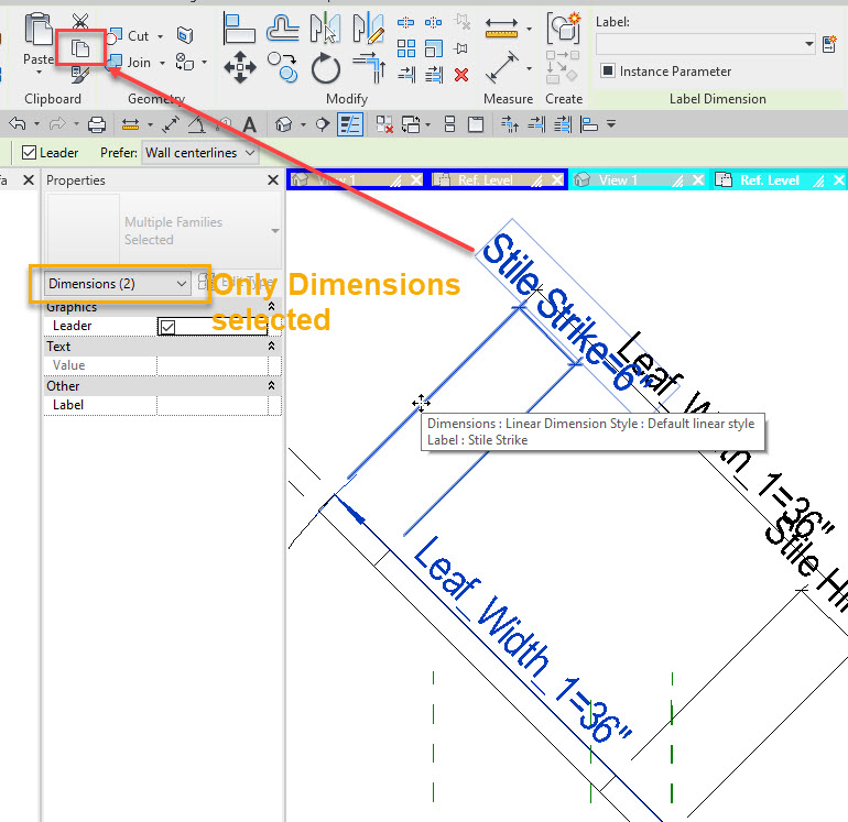
Over the years I have tried several ways to copy parameters from one family to another. I have created solids or reference planes added dimensions and then copied all of that to the clipboard, then pasted to another family, and deleted what was pasted. I have used Dynamo and other add in tools as well. This week I realized you can simply copy the dimension, then paste into the other family. No need to go back and delete everything as nothing will actually paste but the parameter names.
Reading a discussion in the Autodesk forums today I realized that this topic is something that comes up often and not everyone may know if this solution so it deserved a post.
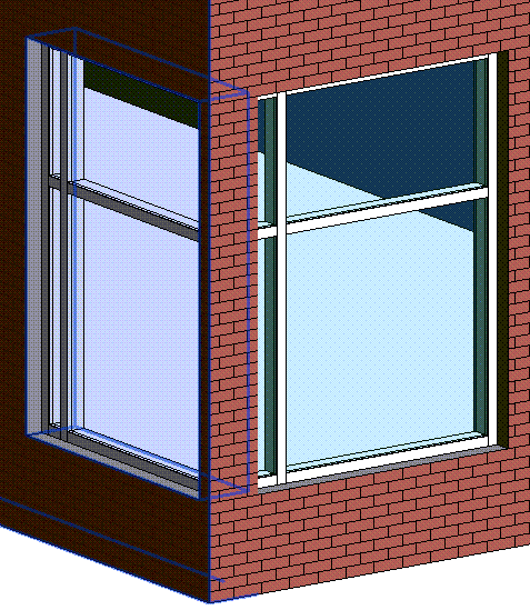
When modeling a curtain wall, no matter as a window, storefront or as a curtain wall in at a corner there can be an issue where the automatically embedded curtain wall cuts the openings on each wall but fails to cut the end portion out of the wall, as seen in figure 1.
Figure 1
I have seen several suggestions to edit the profile of the wall, or add an in-place void or use the wall opening command. All of these suggestions work but if the curtain wall changes then the user has to change the element they used to cut the opening.
There is another way…
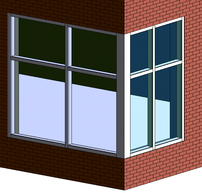
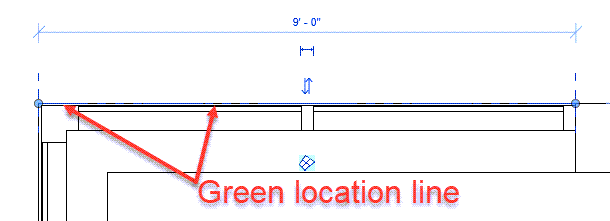
There isn’t any need for edit profile or adding openings or any crazy work around for that. Curtain walls look to their origin point (green dashed line see Figure 5) to understand where to cut the walls. That origin of the curtain wall must lie within the wall, when that line is set with in the wall it will cut the opening at that location. If that line lies on the face of the wall then it will cut the wall at the face, removing the little portion everyone hates as seen in figure 2.
Figure 2
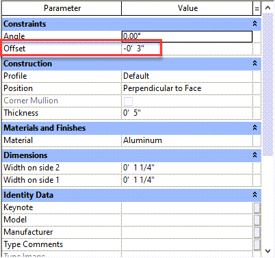
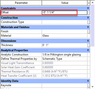
How does a user make the wall align with the face yet have the panels and mullions set back from the face? By using the offsets built into the System Panel and Curtain Wall Mullion families. The curtain wall mullions, regardless if they are rectangular, corner or round will have an Offset value in the type properties, this value will allow for the mullion to be located off the green location line of the wall.
Figure 3
Similarly the default system panel for curtain wall panels have the same value.
Figure 4
If these values are set such that the curtain wall itself can be drawn at the face of the wall yet the mullions and panels are set off of that Revit will cut the walls accordingly. Plus it is an easier way to get a consistent set back for all of the curtain walls.
Figure 5
There is only one glitch to this process. If the curtain wall is modeled on the face of the host wall to start. It doesn’t cut the opening, it must be modeled inside the wall then moved or aligned to the face.
While setting up an engineering firms template this week I had a brainstorm while working on creating the Composite Metal Decks.
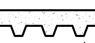
Typical Composite Deck
While I was setting up their structural metal deck and loading in the profile for “Slab Metal Deck” it dawned on me, these profiles could also be used for other things besides metal deck. Often we want to see floors with 2×6 or tongue and groove decking. Yet we may not want the overhead of modeling these elements (Yes I have modeled them as beam systems in the past).
Wood Decking
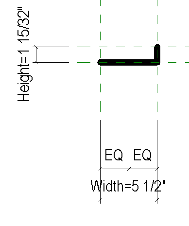
With that thought I tried to create a simple Structural Deck Profile that was simply an “L” shape. I only needed the vertical line to represent the 2x members but knowing their would have to be a horizontal line that would represent the width of the the 2x member.
Broken Profile
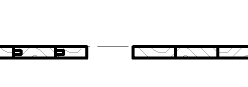
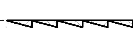
However I realized that when these profile families are loaded into the project and assigned to a floor Revit attempts to connect the ends of the lines in the profile, Thus creating undesired results
Results from Broken Profile
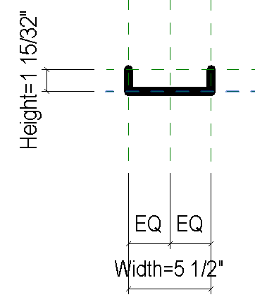
This means the profiles have to have lines on the left and right end in the same location so Revit can connect them without adjusting the profile.
Correct Profile
With that in mind I haven’t found a way to get a tongue and groove to work properly. I am on the fence if I like the line between the groove and tongue but I think it may be worth it. The profile in conjunction with a drafting cut pattern returns a pretty good result.
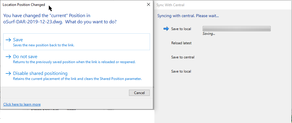
When Autodesk introduced their cloud platform BIM360 Docs for Revit (formerly BIM360 Team, formerly A360, formerly Skyscraper). There was an issue where if a linked file using shared coordinates was moved (mostly .dwg files), thus modifying the shared coordinates, the file would fail to synchronize. The user had to use the save command first telling Revit to ether save the “current” position, do not save or disable shared positioning. This was a bug where this dialog box was not allowed not come up during a synchronize process and only during a save process. Well in 2020.2 I can say this is no longer the case. Today I added several .dwg files using shared coordinates and when I went to synch the dialog box popped up. Thus saving me from yelling at Revit and having to go back and save the file first.
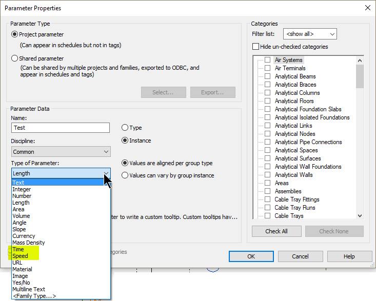
In Revit 2020 Autodesk added a new tool for Path of Travel. One undocumented added bonus to this is it added two additional parameter types: Time & Speed. I noticed these when setting up a new template for a client and I was adding in a new Project parameter.
As expected these are also there when creating family parameters.
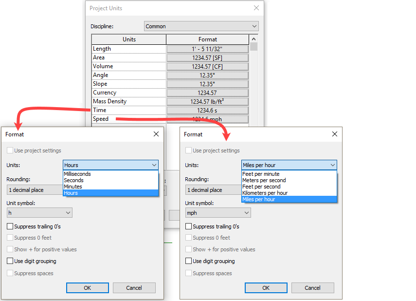
Of course if this new parameter type shows up for both families and projects then we must be able to set units for them. When going to Project Units there will be options to adjust the settings, which would obviously affect the Path of Travel tool but any custom parameters added using this value.
Off the top of my head I haven’t figured out exactly how to use the values. Originally I had though of contractors being able to add time values to elements but since the units are maximized at Hours not sure how it will work. I then thought of the clock families I have created. I also realized that if the Time value is set to Hours then a user can enter the seconds as 600 s and it will convert to Hours, however the value for minutes is “min” which I can see getting confused with minimum values, or is that a hack for values where you don’t want to type in min after every input (I think that is a terrible idea but that is what came to mind first)
At any rate these are here to experiment with and see what values we can use them for.