For many years I have been asked the question “Is there a way in Revit to only show the core of the wall?”. Recently this question came up yet again during a session of Revit Radio, but this time it came up right after an example with parts. So this got me thinking could we break up a wall into parts and then use filters to somehow turn off those parts. Ironically at the same time Dezi was working on a similar situation to only show the core of the Architects walls through a linked model. So we sat down and worked on this together and came up with a solution, YES you can only show the core. Finally the answer everyone has wanted to hear to this question over the years.
The first step to this procedure is to send Dezi and I some nice bottles of wine as a thank you…. Ok just joking I am writing this while high in the mountains of Alma Colorado while having a nice evening and running out of drinks and not wanting to drive into town to get more…
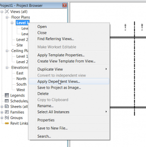
The real first step is to select the walls and select the Create Parts button . This will divide the layers of the wall into individual parts. It will also set your view properties “Parts Visibility” to Show Parts.
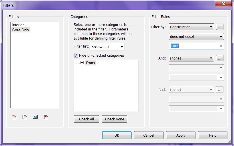
The next step is to create a filter so that the other parts of the wall can be hidden. On the View tab, Graphics panel, select the Filters button. Name the filter, assign it to Parts for the category, set the Rules to be Construction >> does not equal >> Core.
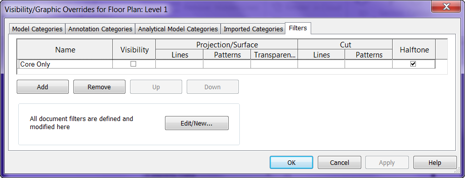
Add this filter to your view via the Visibility Graphics >> Filters tab and un-check visibility
It could also be filtered by materials or whatever else is needed, I just used Construction property for this post. Dezi also found out that this will work nicely through linked files to turn off certain parts of the Architects wall for her Structural model.
If you want to display all the layers of the wall you don’t have to edit the Filters again just change the “Parts Visibility” property to “Show Original”
Of course there are limitations to this system; the lack of stability with parts in the 2012 release, join conditions can be funky, some walls can’t have parts applied to them period. So when I say yes we can use this to display only the core I guess it will depend on the stability of parts and wall joins. Just a thought for everyone to try let me know how well it works for your conditions.
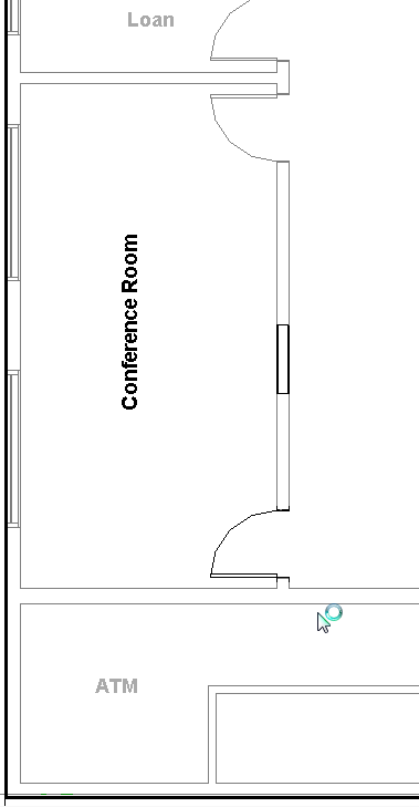 When working with phases in Revit one complaint is that you can’t show rooms from a previous phase. This is where composite views on sheets works like a charm. Composite view means more than one view placed on top of each other on a sheet. Set up a plan view with the phasing set to New Construction and set the Visibility Graphics as desired. Set up another view with the phasing set to Existing, only display Rooms and Room tags in this view, only tag the existing rooms to be displayed (Note: in Visibility Graphics the Room Tags can be set to Halftone to display similarly to existing phase). Once both of these views are created drag the views onto the desired sheet. Revit will align the files nicely on the sheets. The last step is select one of the views, usually the existing room tag view, and change the viewport to one with out a view title. The room name only view can also be duplicated with dependancies if you need to show the room names on more than one sheet.
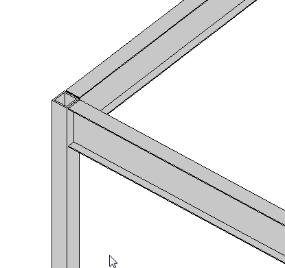 If you have a a beam connected to a column, similar to what is shown (element types can vary), there is a value in the instance properties of the beam called “Start/End Attachment Type”. This property can be changed to End Elevation or Distance, by default the value is End Elevation. End Elevation maintains the value of the beam to the placement level and Distance orients the value to the join location on a column. So if you are wanting the beams to move up and down with the top (or bottom) of a column then you simply change this value to Distance.
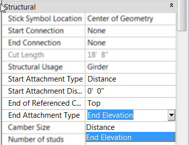 Once the value is changed to Distance then you will see two new properties show up for the beam, “Attachment Distance” and “End of Referenced Column”. Attachment Distance option allows a user to put in a value for an offset of the beam to the top of the column, so that the beam will still move up and down with the column just be that given value away. End of… allows the beam to be either associated to the Top or Bottom of the column.