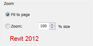
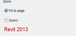
So in Revit 2013 I noticed a small little change to the print setup dialog box. This change is minor and doesn’t really affect any options but will be nice for clarification. In 2012 and earlier when you changed the Zoom option to “Fit to page” the % size dialog didn’t change. This could cause confusion where users thought it would fit to page but at 100% of the view. Now in 2013 when you change to “Fit to page” the % size option disappears. Not a big deal but I have had questions in the past on this and hopefully it will make things more clear.
Tag Archives: Tips
Steering Wheel Features
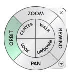 While using the steering wheel command in Autodesk products, (I have only tested this with Revit and Navisworks), some of the features have additional options or tools associated with them. For those of you who haven’t used the steering wheel Shift+W will bring it up.
While in the Orbit feature of the steering wheel, the pivot can be changed on the fly by holding the CTRL key down. Now you can locate the pivot point and then release the CTRL key and continue to orbit the model.
Before using the Zoom feature you can hold the Shift key down and it will take you into zoom window option instead of dynamic zoom.
While using the Look feture you can use the arrow keys to walk through the model, similar to W,A,S,D on first person video games. You can also use the Shift key before look to select a face of an element to focus on to.
With the Rewind tool not only can you see all of the previous zoom levels you were at but you can also fast forward to a position incase you rewound to far.
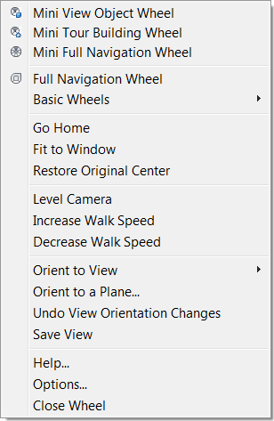
Last but no least you can also right click on the steering wheel and get a list of options, allowing a user to Fit everything to the window, Level the camera, etc.
Revit Basics – Linework Tool
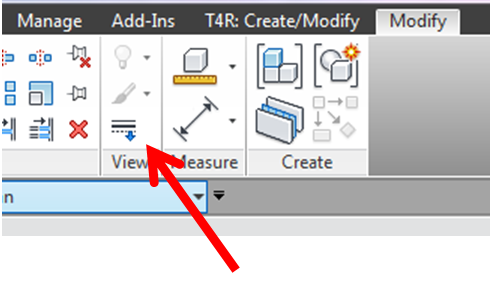
The linework tool is found on the Modify tab, in the View panel.
With this tool a Revit user can override the graphical style of a model element, i.e. change something from a solid to a dashed or hidden line, or to make a line invisible all together. Any line style in the project may be used, plus a few default out-of-the-box options. Furthermore, each edge, side or line of an element may be independently overridden (so only one side of a wall, or one edge of a slab, etc).
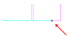
Once a line is overridden grips will appear at the ends of the lines. These grips can be drug one way or another such that only part of the line is overridden. The catch is that these grips will only appear when the linework tool is activated, and when the overridden line is selected.
What if more than one portion of a line is to be overridden? Use the line work tool again and additional grips will appear that can now be drug independently from the first set.
One final question with this tool is how would one put the element back to its default style? No, one would not have to delete the element and remodel it, and it is never a good idea to just draw lines over it.
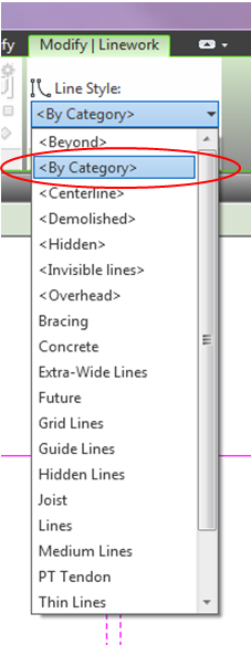
The answer is to use the linework tool once again, but instead of choosing a line style, choose “By Category” and click on the elements to be changed back to their default style. (It will be possible to select only overridden elements, even the ones that were made invisible).
Override Graphics in View 2013 Dialog
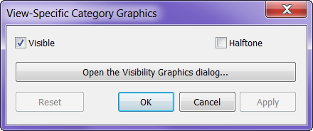
In Revit 2013 I noticed that when you right click an element in a view and select “Override Graphics in View” by category it brings up a new dialog box instead of taking you straight to the Visibility Graphics dialog box. This is a nice undocumented feature that can speed up the process with less clicks.
Detached from Workplane Fix for Beam Systems
I find the “Element will be detached from its associated plane” warning the perhaps second most annoying warning (the beam slightly off axis is the most annoying).
Sometimes there isn’t a good (read quick) way to fix this warning so we just leave it. Recently I have been working on a project where roof elevations have been changing quite a bit and occasionally the beams in my beam systems will detach themselves from their workplane…they are still in the correct location, but that warning now exists in my project. I have been fixing this by editing the beam system and clicking “reset system”, which doesn’t change anything I can see, but it quickly reattaches the beams in the system to the workplane that was originally set when the beam system was created.
I thought I would share this in case others could use it.

