Tag Archives: Revit

Revit 2013 – Override in View By Category

This is a follow-up, or an expansion on our earlier post on this same topic.

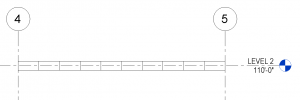
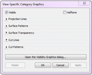
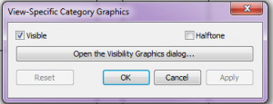
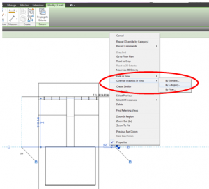
As noted before, a handy new undocumented feature in Revit 2013 is that selecting an element, right-clicking, and navigating to Override Graphics in View>>By Category no longer simply opens Visibility Graphics. Instead, a new dialog box appears.


 Depending on which element was selected, and what visibility settings are available, different options appear in the dialog box.

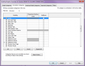
This dialog box is handy for a couple reasons.  First, any overrides assigned within the dialog box will apply to the Visibility Graphics.  Next time the Visibility Graphics window is opened, the overrides will be there.  And second, if one prefers to just go to the VG window, the handy “Open the Visibility Graphics dialog…” will not only open VG’s, but it will automatically navigate to the selected category – super convenient.  The screen shot below shows the state of the VG dialog box when a level was selected and the “Open the Visibility Graphics dialog…” button was clicked.

Cross-Section Rotation Quirk

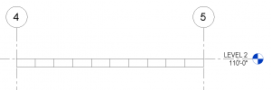
I was recently doing a quick little job for a client and in modeling the structure I needed to show a 2×4 wood framing member turned flat, so I used the OOTB 2×4 and set the Cross-Section Rotation to 90 degrees.  The following is what I got.
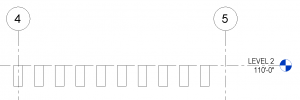
Since I wanted the top of the framing to align with the level, and the above was the result, I was reminded that the cross-section rotation’s base point is the intersection of the workplane and the Lateral Justification, so I changed the Lateral Justification to ‘Side 1’ and got my desired result.
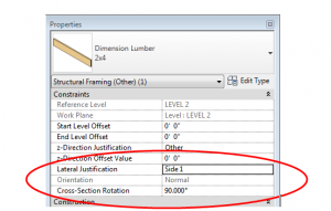
This got me thinking – what if I had wanted to move the framing more than just a little?  It is a known quirk that the z-direction offset doesn’t work quite right when the cross-section rotation is set to anything other than zero, but I haven’t seen any documentation to explain what is really going on so I thought I would figure it out.

The conclusion is this: assuming the cross-section rotation is set to a value, a, if you enter a value, z, into the z-direction offset, the member will move as follows:

Vertical movement = z*cos(a), where up is positive

Horizontal movement = z*sin(a), where left is positive

I could paste a ton of screen shots here showing a bunch of variations, but I encourage you to go play with these settings and see what happens.  Take particular note of the fact that cross-section rotation values greater than 180 degrees causes positive z-direction offsets to cause movements in the negative directions.

So what is the solution?  I would suggest using the start and end-level offsets for z-direction movement.  However, if there is a reason why that is impossible, or if you just want to test it out, the following equations will produce desired results.

For a desired vertical offset, z, a cross-section rotation, a, and assuming no horizontal movement is desired:

In z-direction offset enter: z / cos(a)

And then move the framing member to the right this amount: z*tan(a)

For a workplane that is not horizontal, the above equations work if vertical is taken to be perpendicular to the workplane and if horizontal is taken to be parallel to the workplane.  To get global horizontal and vertical movements, the angle of the workplane would have to be considered, as would the cross-section orientation (Normal vs Horizontal) since each case would require different equations.  Since this topic seems to be complicated enough, I will not go into any more detail on non-horizontal workplanes.

Given my affinity towards math and families, I would love to be able to incorporate these equations into the framing families (since the equations are valid for a 0 degree rotation too), but of course none of these parameters are available until after the element is loaded into a project, so I will put that on hold for now….but I reserve the right to revisit this idea!
Detached from Workplane Fix for Beam Systems

I find the “Element will be detached from its associated plane” warning the perhaps second most annoying warning (the beam slightly off axis is the most annoying).

Sometimes there isn’t a good (read quick) way to fix this warning so we just leave it.  Recently I have been working on a project where roof elevations have been changing quite a bit and occasionally the beams in my beam systems will detach themselves from their workplane…they are still in the correct location, but that warning now exists in my project.  I have been fixing this by editing the beam system and clicking “reset system”, which doesn’t change anything I can see, but it quickly reattaches the beams in the system to the workplane that was originally set when the beam system was created.

I thought I would share this in case others could use it.

Autodesk Building Design Suit 2013

Autodesk said that the Design suites would be available today and they didn’t lie.  However for us die hard geeks we come to expect that to be first thing in the morning when we wake up.  Well it took until the afternoon but they are available for download.  I went to get mine via my subscription site I didn’t look on the Autodesk site directly.


I also found it interesting that there are links for 2009 since the suite started in 2011.  I clicked on the link and it allowed me to download the individual programs that are part of the Building Design Suite.  I had to find something to do while I wait 1 hour for it to download.

Revit Floors Room Bounding

On Monday Steve Stafford posetd about how finish floors can do bad things when passing a model off to the MEP consultants.   I have also seen this cause issues when the architects go to tag their rooms and and the tag won’t display the room information.  The same situation is true as Steve had posted, all finish floors should be non “Room Bouding” in the Revit model.

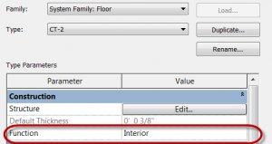
As a good practice I will have architects set the “Function” to all finish floors to be Interior.

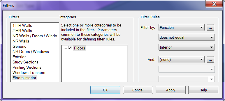
Now that this is set I will create a “Filter” so that it’s “Funtion – does not equal – Interior”.  Then I apply this filter to a 3D view where I turn off the visibility of the filter and only have floors displayed.  Now I can just select all the floors in the view and turn off  the Room Bounding check mark.