Category Archives: Platform

Referenced Bubbles

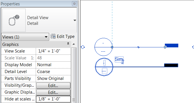
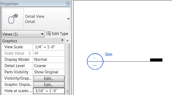
While doing some training today I had a user find a bug in the program that I forgot about.  It has to deal with the “Hide at scales coarser than” value for views.  When a view is not a live view but references another view it doesn’t obey the “Hide at scales coarser than” rules, it will always display. Something to be aware next time you are trying to troubleshoot this issue.


Snap Distances

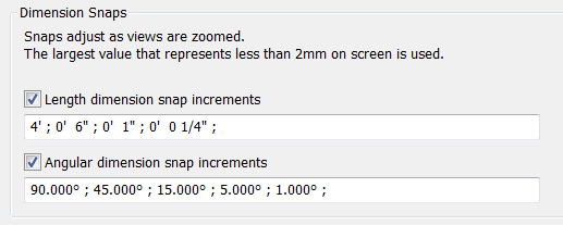
I thought I would follow up from the last post with a small little tip.  When the Nudge command is used it looks to the values that are set in the Dimension Snap setting dialog.

As the description in this dialog box states: When the mouse is moved 2mm on the screen it will snap to the length dimensions that are closest to that zoom resolution, this is also true for the Nudge command.  A little known trick to this dialog box is to adjust it often.  I have heard many times that AutoCAD Architecture or other programs are nice because when inserting doors I can set a desired value and the doors just snap to that distance.

  Revit can do the same if this dialog box is used, Change the 6″ value to say 5″ (127mm) and then start placing doors, they will snap this distance from a desired corner.  I will also change that value to 8″ when  I am working with a brick or masonry wall, now when I model the wall is the correct length.  Of course verify that the temporary dimensions are also set approiately to what you need as well.

Nudge

My tip today is a quick one.  This is something I managed to go years without knowing and so when I noticed myself using it today I thought I would share.  Everyone uses “Nudge”; simply select and object and use the arrow keys to move said object slightly.  But what if you want to move it more than just a little bit?  Hold down the shift key and the nudge distance will increase by a factor of 10.

Show Hidden Lines

This is a tool that seems to be underutilized when I visits firms, yet a tool that is very useful when it comes time to setting up construction documentation.  If there has ever come a need to show one objected hidden behind another, there is a tool for that.  On the View tab in the Graphics panel there is a command called Show Hidden Lines, this tool allows for an element to be picked an that needs to see the dashed line through, then the element to be hidden.

As usually the status bar will always display the steps needed to accomplish a command.

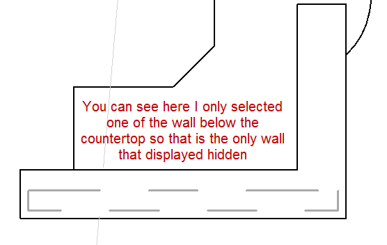
One tip I usually talk about when using this command is to go into Wireframe, other wise it is really hard to get the element that is being hidden. Once the command is done the view can be put back into Hidden Line mode to see the effects.  In the example below I did this with a partial height wall that was being covered with a counter top to display the wall below.
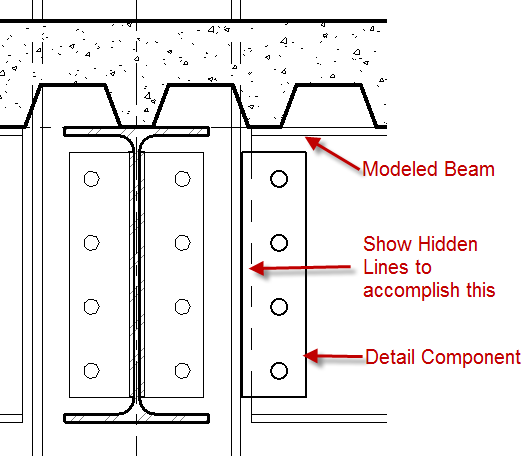
Another little tip about this tool is that is also works with detail components and modeled elements.  A modeled element can be displayed hidden through a detail component that has a masking region built into it.  The example below shows this for a plate detail component over a modeled structural beam.


Section or Details in Legends

I run into this question usually on a weekly basis so I thought it would be a good post.

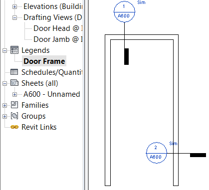
When creating a legend, say a door frame legend, and there needs to be a reference a detail in that legend Revit wont allow it.  The section and callout commands are greyed out.  Don’t use a dummy bubble (never ever use a dummy bubble) instead go to another live view of the model (i.e. section, plan, elevation), choose the correct command section or callout, and do a reference view.

Copy that view reference to the clipboard, switch to the legend view and paste from the clipboard.