The Autodesk wiki help site now has the Revit 2014 on it as well as some of the other programs. If you want to read the official what’s new, according to the help file, then check out the links below. I do like the way they have it broken down for BIM managers, Installation etc.
Category Archives: Platform
Revit 2014 New Features
Anybody in the blogging world isn’t going to compete with the thoroughness of David Lights posts about new features in Revit. I would just like to add a few comments on some of my favorite new features:
Alternate dimensions: Although this hasn’t been that big of an issue I work with many clients that do work both in metric and imperial units so this little feature is a nice and welcome addition. Having the ability to not only show the alternate dimensions but have the choice of where they are located will be big for some of my clients.
New Material UI: This was one of the most frustrating changes in 2013 and made for huge losses of time in the delay and craziness that it was. Well it is now back to a tabular format which is not only faster bust just makes more sense overall.
Double Click Options: The fact that when you double clicked on any family that family was then opened in the family editor was probably the biggest frustration to users that I spoke with. In 2014 we now have options for a multitude of things to happen when an object is double click on. This is a great feature and will make, at least myself happy, but many others as well. No more trying to edit a tag and ending up in the family editor.
Selection enhancements: Tired of having those new users move linked files around, not knowing about the press and drag feature and moving numerous other elements around? In 2014 there is now a select setting that will allow for links, underlays and pinned elements to not be selected. (caution on the pinned elements, beams in a beam system, mullions on a curtain wall can be pinned elements. So if you can’t select those elements you might want to check the settings)
Schedules: For anyone who has met me knows I am a total geek when it comes to schedules. We they have had a major overhaul and there are many changes with them. Including more categories (thank you detail items and generic model additions) and a new conceptual ribbon for the numerous editing changes we have available.
If you are looking for more information on any of the above feature check out David post or the Autodesk site.
Temporary Dimensions – Tips
Everyone who has used Revit often uses temporary dimensions, and even this simple tool has a few tips. To activate a temporary dimension simply select an element on the screen. Sometimes temporary dimensions don’t immediately display, this can happen if the element selected are being monitored, locked etc. If this is the case look for the activate dimensions button in the options bar. Once the temporary dimensions are available the middle grip on the witness line can be selected(called the move witness line grip), and it can be drug to another object. Another option is to simply click the witness line which will cause it to cycle from one face of an elements, to the center, or to the other face (this works for some, not all elements i.e. walls). Input can also be entered once the temporary dimensions are activated, however not everyone knows formulas can also be input. For example if an angle is activated and the rise and run is known but not the angle, then entering “=atan(rise/run)” or “=atan(4/12)” will calculate the angle and will adjust the graphics accordingly. Another temporary dimensions tip is to start dragging one end of an element, then start typing in a number. This will automatically activate the temporary dimensions and the entered value will be applied.
Rotating Detail Families
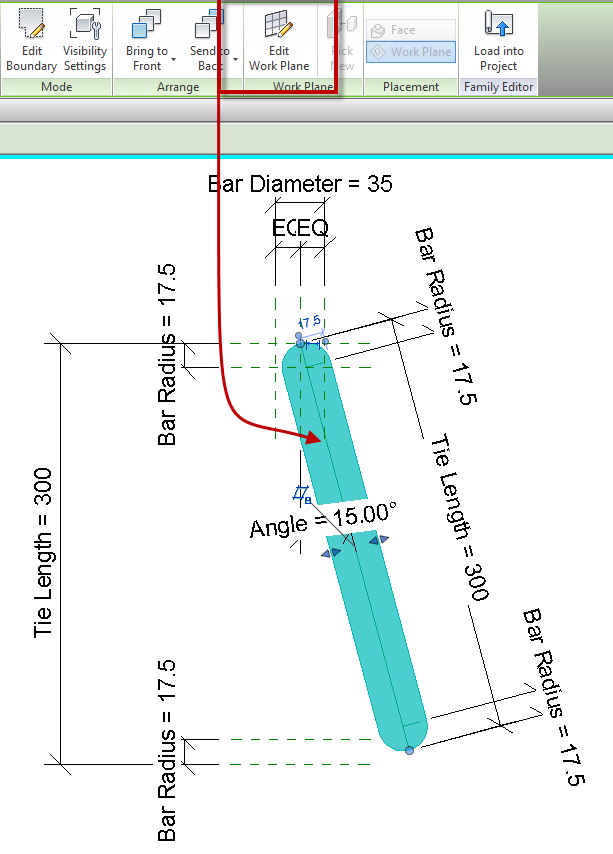
When creating a filled/masking region inside of a detail component family a work plane can’t be specified before, or during the sketch mode. My work around to this is to create a simple rectangle as the region, finish the sketch and then edit the work plane. Once the work plane is set outside of the sketch, edit the sketch and draw it accordingly. The only real reason this becomes useful is the filled region needs to have a rotation value, setting the region to be on a reference line will make it less likely to break.
Convert all Grids to 2D
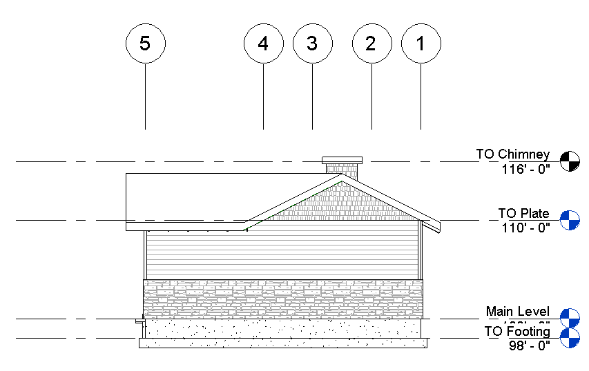
Sometime in projects an elevation needs to have the grid lines above the building.
In order to accomplish this the 2D extents of the grid lines need to move not the 3D extents, because if the 3D extents are moved then the grid lines disappear in the plan views. There isn’t any need to click on each grid and hit the 3D grip to convert it to 2D. Simply enable the crop region, move the crop region so that it crosses over the grid lines. This will automatically convert the grid extents to 2D. Then drag the view specific grip (solid dot) on one of the grids, and all of them will move. Then propagate extents to the other views. If they need to go back to 3D then Right Click on each grid and select “Reset to 3D Extents”.
This is also true for Levels.


