A way to tag the top of footing elevation is a question that comes up often. Below is a procedure that I came up with a year or so ago. I wrote an article for AUGIWorld last year on this issue as well. This is a condensed version of the article, feel free to follow the link to read the full version. One item to note here is that conditional formatting broke in the 2013 release – so use 2012 to create the schedules, and then upgrade, and hope the problem is fixed in 2014.
Step One: Create a Shared Parameter
Create a shared parameter for the top of footing elevation that will appear in the foundation tag. Add the the parameter as a project parameter and apply it to structural foundations. There are two reasons to use a project parameter here: first, using a project parameter will avoid the need to edit all of the structural foundation families (and re-editing them if updates occur), and second, elevations of elements are not available until they are inserted into a project, so there is little benefit to putting an elevation parameter into a family.
Step Two: Create a Foundation Tag
Create a new, or modify an existing, foundation tag that references the new top of footing elevation parameter. Ultimately the elevation parameter will have to be input manually, so once the new tag is created and loaded into a project (or into a project template), one could choose to go no further in this process. However, the remaining steps will add intelligence and improve upon this process such that the elevations are more easily managed.
Step Three: One More Shared Parameter
In order to avoid manually entering and managing them, the top of footing elevations will be calculated using the bottom elevation and the foundation thickness. This calculation will be carried out in a schedule. Unfortunately, the thickness parameter in the out of the box isolated footings is not a shared parameter, so it cannot be scheduled (wall footings and foundation slabs do not have this problem). As a result, one more shared parameter is required. Regrettably, this parameter has to be added to each family; simply replace the existing thickness parameter with the new thickness shared parameter. This will have to be completed in every isolated foundation family.
Step Four: Schedule the Foundations
Create a schedule that includes all of the structural foundations. Depending on the complexity of the project, some filters may be necessary to show only the desired footings. Which fields to include is at the discretion of each user, but at the very least include footing type, elevation at the bottom, the new top of footing parameter, and all applicable thickness parameters (each of the foundation families have their own thickness parameter). For simplicity, this process will only be concerned with one of the foundation families, the isolated foundation; however, it is possible to include and manage all of the structural foundation families in one schedule.
Step Five: Add a Calculated Value
Add a calculated value that will report the actual top of footing elevations for each footing. Please note that the bottom elevation parameter is based on the project coordinates, so if elevation zero is not the same in both the shared and project coordinates, then this will have to be incorporated in to the calculated value. In this example, this has been handled by adding a parameter called “Datum” and setting it to the proper elevation. Setting the datum value can be achieved quickly by altering the sorting/grouping settings to group all of the footings into one row and then changing the value all at once.
To calculate the actual top of footing elevation, add the foundation thickness to the elevation at the bottom, and then add the datum value, if applicable. The calculated parameter is illustrated in Figure 1.
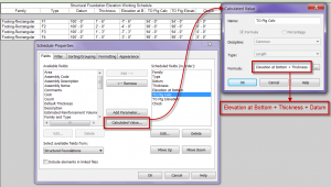
Figure 1 – Calculated Parameter with Datum
With adding the calculated value, the accurate top of footing elevation will appear in the schedule next to the top of footing shared parameter that needs to be manually input. A Revit user could then simply input the proper value to match the calculated value and the elevation would then appear in the foundation tag. A suggestion here would be to group the foundations by their calculated top of footing elevations, and then input all of the values, thus only requiring that a user type any common elevations once.
Ending the process at this step would provide a simplified way to manually enter all of the top of footing elevations, but it would not entirely solve the issue that the footings may move and the elevations will have to be managed. Yes, having the accurate elevation immediately available will aid in the management process, but it could be even easier.
Step Six: Add a Check Value
Add another calculated value to the schedule that is called “check”. Make this value be the difference between the manually input value and the calculated elevation value. Finally, use conditional formatting to turn the input elevation cell red if the “check” cell is not equal to zero, see figures 2 and 3.
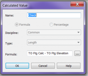
Figure 2 – “Check”
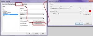
Figure 3 – Conditional Formatting
The “Check” column can be a hidden field, if so desired, since including this step causes any incorrect values (not the check value) in the schedule to turn red, thus making it extremely easy to identify and to edit the incorrect values.
Another approach is to make the “check” value a yes/no parameter, instead of length, that tests if the calculated value equals the manually entered value. The conditional formatting can then be set to turn the inputted value red if the yes/no check parameter returns a “no”. The yes/no return may be a more straight forward test output, but knowing the total difference between the calculated and the manually entered value may be useful. Either method will work, but one or the other may be of more use to the user.
Once the schedule is expanded for the other structural foundation values, a calculated value, as well as a separate check field will be required for each structural foundation family. However, the conditional formatting can include multiple criteria, so simply add a test expression for each foundation family to the inputted top of footing elevation’s conditional formatting.
Step Seven: Use the Schedule
After the schedule is completed, the only remaining step is to use it, and to remember to occasionally check that values are not coming up red. When the foundations and the tags are originally placed, the elevation field will be blank, so that helps to remind the user to visit the schedule. Then, as long as the schedule is checked prior to issuing the construction documents, the structural engineer can be confident that the top of footing elevations are accurate. The schedule also adds a level of automation that will reduce errors. Figure 4 shows tiled windows of the completed schedule (the check column is shown here, but would typically be a hidden field, as previously noted), and the foundations with their tags.
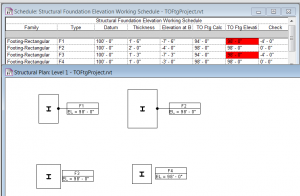
Figure 4 – Completed Schedule and Footings with Tags

