Category Archives: Revit

Revit Posts

Revit 2014 New Features

Anybody in the blogging world isn’t going to compete with the thoroughness of David Lights posts about new features in Revit.  I would just like to add a few comments on some of my favorite new features:

Alternate dimensions:  Although this hasn’t been that big of an issue I work with many clients that do work both in metric and imperial units so this little feature is a nice and welcome addition.  Having the ability to not only show the alternate dimensions but have the choice of where they are located will be big for some of my clients.

New Material UI: This was one of the most frustrating changes in 2013 and made for huge losses of time in the delay and craziness that it was.  Well it is now back to a tabular format which is not only faster bust just makes more sense overall.

Double Click Options: The fact that when you double clicked on any family that family was then opened in the family editor was probably the biggest frustration to users that I spoke with.  In 2014 we now have options for a multitude of things to happen when an object is double click on.  This is a great feature and will make, at least myself happy, but many others as well.  No more trying to edit a tag and ending up in the family editor.

Selection enhancements:  Tired of having those new users move linked files around, not knowing about the press and drag feature and moving numerous other elements around?  In 2014 there is now a select setting that will allow for links, underlays and pinned elements to not be selected. (caution on the pinned elements, beams in a beam system, mullions on a curtain wall can be pinned elements.  So if you can’t select those elements you might want to check the settings)

Schedules:  For anyone who has met me knows I am a total geek when it comes to schedules.  We they have had a major overhaul and there are many changes with them.  Including more categories (thank you detail items and generic model additions) and a new conceptual ribbon for the numerous editing changes we have available.

If you are looking for more information on any of the above feature check out David post or the Autodesk site.

Tie Beams to Columns

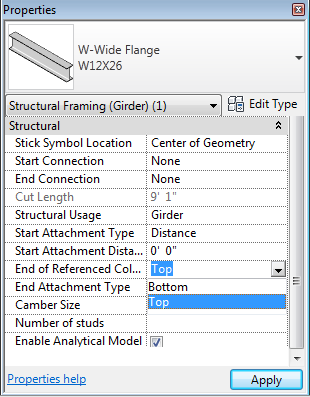
When first using Revit Structure it can be frustrating that when the height of a column moves or changes, the beams that were associated to the top of the column didn’t change elevation with the column.  This condition was changed a few releases ago but it still seems to be a rarely utilized property.  If a beam is modeled to a column, two properties are applied: Start Attachment Type and/or End Attachment Type.  These values, when set properly, allow the beam to move up or down with the column.  By default the values are set to End Elevation, which doesn’t associate the beam to the column.  For the beam to be associated, this value should be changed to “Distance”.  Once distance is selected then two additional properties appear: Attachment Distance and End of Referenced Column.  The distance value can be used to adjust the end of the beam such that it isn’t aligned with the end of the column.  Unfortunately, this value will always move the beam away from the ends towards the center of the column and not outside the ends.  End of Referenced Column can either be set to the top or bottom of the column so the beam moves accordingly.

Beam End Symbols

With beam members there has always been the ability to show a start or end connection symbols.  In the early releases connection symbols were limited to Moment Frame and Cantilever Moment.  These symbols could have any graphics desired, but they were the only two options.  In the last few releases this feature was opened up so many connection types and custom symbols can be created.  Several firms have used this feature, but since it has been opened up, the applications can go beyond the classic option.  Firms could use this feature for all types of building construction.  For example, it could be used in wood construction to show the different types of hangers and/or fasteners in plan graphics.  Customizing this feature is a multistep process, but once added to a template, the options will be available for the entire team to use.

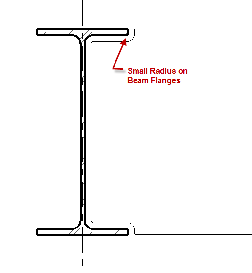
  • The first step is to create the connections symbols.  There isn’t a template specifically designed for this, so start with a generic annotation family.  Then, using the Family Category and Parameter button, change the family type to be Connection Symbol.  The intersection of Reference Planes is the insertion point, which is the end of the beam.  The symbol should be drawn to the right of the insertion point.  There is also an option for “Automatic Cutback for Beams and Braces”.  This option allows the symbol to add an additional cutback to the beam’s symbolic line in the project.  If the intent is to have the  symbol be added directly to the beam line, this should be unchecked.
  • Once the symbol is created, load the family into the project, or project template.  In Structural Settings, go to the Symbolic Representation Settings tab and add a new Connection Symbol for Breams and Braces.  Once the new Connection Type is created, choose the appropriate symbol.
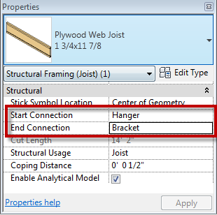
  • Now when a beam is created the new options will be available for connections within the beam instance properties.

All of the above is also applicable to structural columns connections.

Temporary Dimensions – Tips

Everyone who has used Revit often uses temporary dimensions, and  even this simple tool has a few tips.  To activate a temporary dimension simply select an element on the screen.  Sometimes temporary dimensions don’t immediately display, this can happen if the element selected are being monitored, locked etc.  If this is the case look for the activate dimensions button in the options bar.  Once the temporary dimensions are available the middle grip on the witness line can be selected(called the move witness line grip), and it can be drug to another object.  Another option is to simply click the witness line which will cause it to cycle from one face of an elements, to the center, or to the other face (this works for some, not all elements i.e. walls).  Input can also be entered once the temporary dimensions are activated, however not everyone knows formulas can also be input.  For example if an angle is activated and the rise and run is known but not the angle, then entering  “=atan(rise/run)” or  “=atan(4/12)” will calculate the angle and will adjust the graphics accordingly.  Another temporary dimensions tip is to start dragging one end of an element, then start typing in a number.  This will automatically activate the temporary dimensions and the entered value will be applied.