Square feet per foot dialog

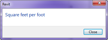
I was creating a schedule key today for and abbreviation list, when this dialog box popped up. 

Can I ask what this dialog box means and why it came up when I was in a text value in a schedule key.  I love Revit warning some times, they are just puzzling.  I think the programmers but them there to make us ponder and laugh during our busy days.

Detailing- Guide Grid

In Revit I sometimes see users having difficulties or just complaining about detailing, either over the model or standard details, and knowing where and how large of an area they have to detail in.  In my last web-cast Detailing in Revit Part 1 I used a family that I have had for years and it sparked a lot of intrigue.  I thought I would discuss how it was created and the benefits of the family.

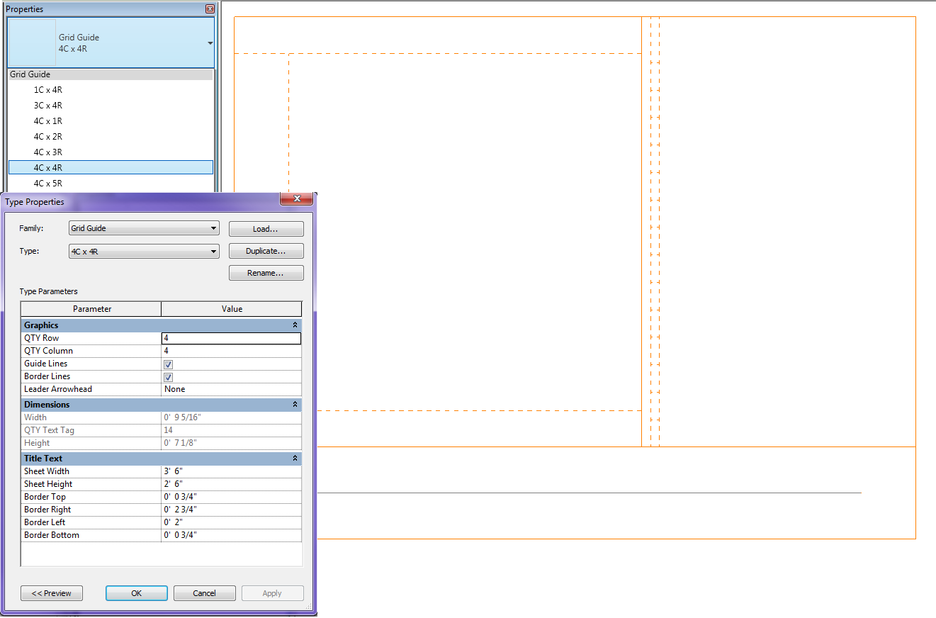
My family is called Guide Grid.rfa and it is used to see the available space for detailing in a view.  This family is created as a generic annotation family so it will scale itself as the scale changes.  It is completely adjustable for titleblock or sheet size per project.  This value may have to be adjusted on a project by project basis, assuming the title blocks are always consitent.  There are also types in the family so a user can decide if they are working with 4columns wide by 4rows high etc.  The size of the box is determined by the sheet size and the row/column quantity.  Once the correct family type is placed in a view the user now knows exactly where to detail and if it is a live view how large to make the crop region.  When it comes time to print just open the type properties of the family and un-check the lines so that there isn’t any orange lines when printing.  Please download the family and let me know how well it works for your company.

Framing Orientation

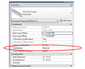
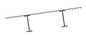
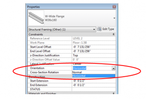
This is one of those Revit basics that has been forgotten, or perhaps never learned.  In the instance parameters for structural framing members, there is a parameter called “Orientation”.

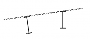
The framing member is only affected by this property if it was modeled on a sloped work plane.

The default orientation is normal – normal to the work plane.

If the orientation is changed to horizontal, the beam will rotate such that the flanges are horizontal.

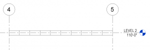
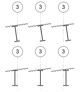
One item of note is that the rotation point is at the intersection of the top of the beam and the lateral justification (Side 1, Center, or Side 2), so if perfect accuracy is required, the beam may have to be shifted down.  The screen shot below shows how the different combinations of a horizontal orientation interacts with the Lateral Justification.


Revit 2013 – Override in View By Category

This is a follow-up, or an expansion on our earlier post on this same topic.

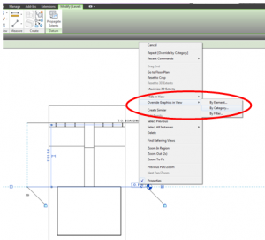
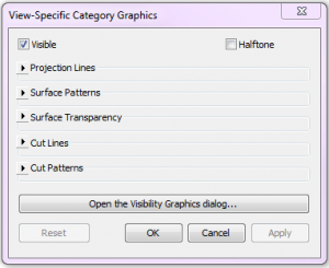
As noted before, a handy new undocumented feature in Revit 2013 is that selecting an element, right-clicking, and navigating to Override Graphics in View>>By Category no longer simply opens Visibility Graphics. Instead, a new dialog box appears.


 Depending on which element was selected, and what visibility settings are available, different options appear in the dialog box.

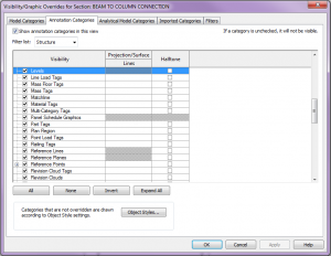
This dialog box is handy for a couple reasons.  First, any overrides assigned within the dialog box will apply to the Visibility Graphics.  Next time the Visibility Graphics window is opened, the overrides will be there.  And second, if one prefers to just go to the VG window, the handy “Open the Visibility Graphics dialog…” will not only open VG’s, but it will automatically navigate to the selected category – super convenient.  The screen shot below shows the state of the VG dialog box when a level was selected and the “Open the Visibility Graphics dialog…” button was clicked.

Cross-Section Rotation Quirk

I was recently doing a quick little job for a client and in modeling the structure I needed to show a 2×4 wood framing member turned flat, so I used the OOTB 2×4 and set the Cross-Section Rotation to 90 degrees.  The following is what I got.
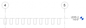
Since I wanted the top of the framing to align with the level, and the above was the result, I was reminded that the cross-section rotation’s base point is the intersection of the workplane and the Lateral Justification, so I changed the Lateral Justification to ‘Side 1’ and got my desired result.
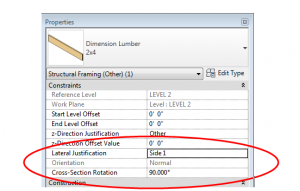
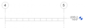
This got me thinking – what if I had wanted to move the framing more than just a little?  It is a known quirk that the z-direction offset doesn’t work quite right when the cross-section rotation is set to anything other than zero, but I haven’t seen any documentation to explain what is really going on so I thought I would figure it out.

The conclusion is this: assuming the cross-section rotation is set to a value, a, if you enter a value, z, into the z-direction offset, the member will move as follows:

Vertical movement = z*cos(a), where up is positive

Horizontal movement = z*sin(a), where left is positive

I could paste a ton of screen shots here showing a bunch of variations, but I encourage you to go play with these settings and see what happens.  Take particular note of the fact that cross-section rotation values greater than 180 degrees causes positive z-direction offsets to cause movements in the negative directions.

So what is the solution?  I would suggest using the start and end-level offsets for z-direction movement.  However, if there is a reason why that is impossible, or if you just want to test it out, the following equations will produce desired results.

For a desired vertical offset, z, a cross-section rotation, a, and assuming no horizontal movement is desired:

In z-direction offset enter: z / cos(a)

And then move the framing member to the right this amount: z*tan(a)

For a workplane that is not horizontal, the above equations work if vertical is taken to be perpendicular to the workplane and if horizontal is taken to be parallel to the workplane.  To get global horizontal and vertical movements, the angle of the workplane would have to be considered, as would the cross-section orientation (Normal vs Horizontal) since each case would require different equations.  Since this topic seems to be complicated enough, I will not go into any more detail on non-horizontal workplanes.

Given my affinity towards math and families, I would love to be able to incorporate these equations into the framing families (since the equations are valid for a 0 degree rotation too), but of course none of these parameters are available until after the element is loaded into a project, so I will put that on hold for now….but I reserve the right to revisit this idea!