Everyone who has used Revit often uses temporary dimensions, and even this simple tool has a few tips. To activate a temporary dimension simply select an element on the screen. Sometimes temporary dimensions don’t immediately display, this can happen if the element selected are being monitored, locked etc. If this is the case look for the activate dimensions button in the options bar. Once the temporary dimensions are available the middle grip on the witness line can be selected(called the move witness line grip), and it can be drug to another object. Another option is to simply click the witness line which will cause it to cycle from one face of an elements, to the center, or to the other face (this works for some, not all elements i.e. walls). Input can also be entered once the temporary dimensions are activated, however not everyone knows formulas can also be input. For example if an angle is activated and the rise and run is known but not the angle, then entering “=atan(rise/run)” or “=atan(4/12)” will calculate the angle and will adjust the graphics accordingly. Another temporary dimensions tip is to start dragging one end of an element, then start typing in a number. This will automatically activate the temporary dimensions and the entered value will be applied.
Automatic Radius for Coping Beams
Rotating Detail Families
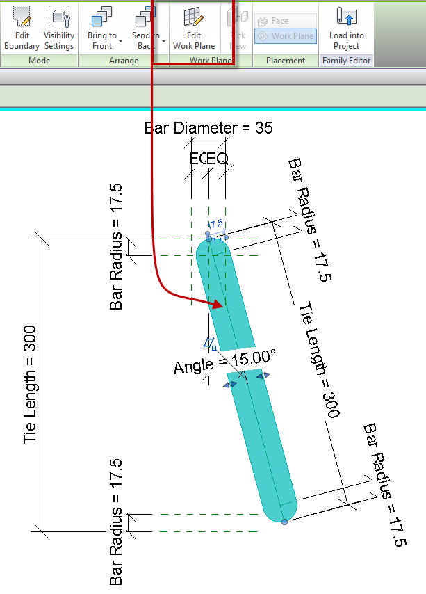
When creating a filled/masking region inside of a detail component family a work plane can’t be specified before, or during the sketch mode. My work around to this is to create a simple rectangle as the region, finish the sketch and then edit the work plane. Once the work plane is set outside of the sketch, edit the sketch and draw it accordingly. The only real reason this becomes useful is the filled region needs to have a rotation value, setting the region to be on a reference line will make it less likely to break.
Convert all Grids to 2D
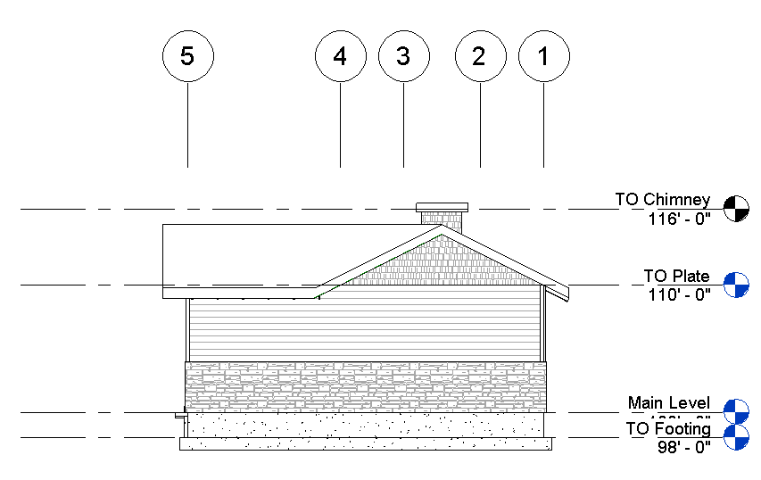
Sometime in projects an elevation needs to have the grid lines above the building.
In order to accomplish this the 2D extents of the grid lines need to move not the 3D extents, because if the 3D extents are moved then the grid lines disappear in the plan views. There isn’t any need to click on each grid and hit the 3D grip to convert it to 2D. Simply enable the crop region, move the crop region so that it crosses over the grid lines. This will automatically convert the grid extents to 2D. Then drag the view specific grip (solid dot) on one of the grids, and all of them will move. Then propagate extents to the other views. If they need to go back to 3D then Right Click on each grid and select “Reset to 3D Extents”.
This is also true for Levels.
Linked Grids and Levels
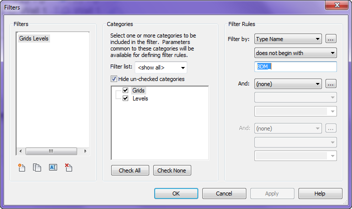
Tired of having to go into the visibility graphics settings and constantly changing the settings in the Revit Link tab to turn off the grids and levels in those files? Or going turning off the workset of the linked model, hoping the consultant didn’t put on other elements on that workset. There is an easier way to accomplish this by using view templates and filters, plus this way it doesn’t matter how bad the file is with worksets.
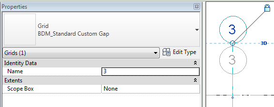
The first step is to make your Levels and Grids unique to those of others. I suggest adding your company acronym to beginning or end of the type name. If your name could be a common acronym, like BU which is part of bubble, then add an underscore, this will make it even more unique.
Once that is done create a filter applied to the Grids and Levels categories, use filter rules for Type Name, does not…, then the acronym entered above. Apply this filter to either the views visibility graphics or the View Filter. Now you never have to worry about the linked grids and levels again.

