Author Archives: Brian Mackey (The Revit Geek)

Revit 2016 R2 reference planes

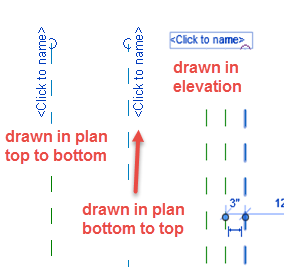
Currently I have been working on family editor training as well as creating content.  With the 2016 R2 update of the minor feature updates are the changes to reference planes inside the family editor.  The first and most noticeable update is the fact that the referenced plane when selected displays <click to name> on both ends of the reference plane.  Two things are new here, first you can select to rename, we no longer are forced to go into the properties to edit the name, second the name is displayed at both ends of the reference plane.

A subtle improvement that may go unnoticed is the fact the name displays differently depending on which view the reference plane has been drawn in.  For example if the reference plane in drawn in plan then the name will be parallel to reference plane in plan, if it had been drawn in an elevation then the name will be perpendicular to plane in plan.  Plus the names will be displayed on the back (or negative value) side of the reference plane depending on the direction they were drawn.

2016 R2 Reference Planes

Revit 2016 Content

With every release of Revit I always use Beyond Compare to compare if/how the families vary from release to release.  This year in the US Imperial Folder (C:\ProgramData\Autodesk\RVT 2016\Libraries) I noticed that there is new organization along with new families for doors.  In 2015 there were 32 families and in 2016 there are 92 families, some of which are hardware families.  I haven’t had the chance to go through and look at these but a long overdue addition for all the architectural users who haven’t developed their own internal library yet.

For structure they have added the AISC 14.1 families that were a subscription bonus last year.  Along with this they have added a few structural tags to go along with some of the new features.

I was however disappointed that they didn’t add or change any of the tags that take advantage of the elevation of floors, roofs etc.

Curved Grid Quirk

There have been numerous posts on curved grid lines and getting them to display as well as many forum responses, even Tim’s post on correcting the height of the curved grids.   I have known about this for years but today none of these tools were working for me to display one single curved grid in a project, this is where I had noticed a quirk with grids.  I was able to reproduce this situation in both Revit 2015 and 2014, I don’t have older versions installed so couldn’t test there.

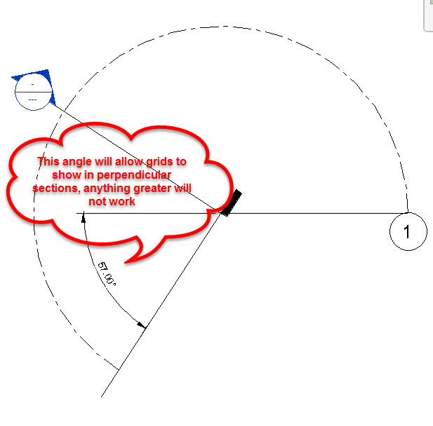
If the 3D extents of a grid line is larger than 237° the grid will not display in any perpendicular section.

Grid_CurveQuirk

If the grid needs to be shown further in plan and still needs to be displayed in sections, then toggling the grid extents to 2D and rotating it around in a plan view is the answer.  However remember this doesn’t have to be done in all the different plan vies, using “Propagate Extents” will push this change into all the other plan views as well.


Loaded Tags

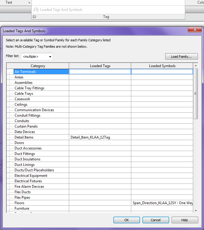
Today I noticed a small feature that either I didn’t notice in the what’s new documentation, ok maybe I just missed it.  In Revit 2015 (currently using update 5) the Loaded Tags command has been replaced with the Loaded Tags and Symbols command.  It is nice to finally be able to set up what symbol will be used for those categories that use them, (i.e.: floor span direction, Structural Path Symbols, Structural Fabric Symbols).  This is documented in the Revit 2015 Help file.

Revit Help

Revit_Loaded_Tags_Symbols

Adaptive Component – Everyday Uses part 5 Roof Cricket

Continued from..

Adaptive Component – Everyday Uses part 4
Adaptive Component – Everyday Uses Part 3
Adaptive Component – Everyday Uses part 2
Adaptive Component – Everyday Uses part 1

Roof Cricket Family

This section of the handout will give step by step instructions to create a variation on the roof cricket family.

  1. Start with the OOTB GenericModelPatternBased template
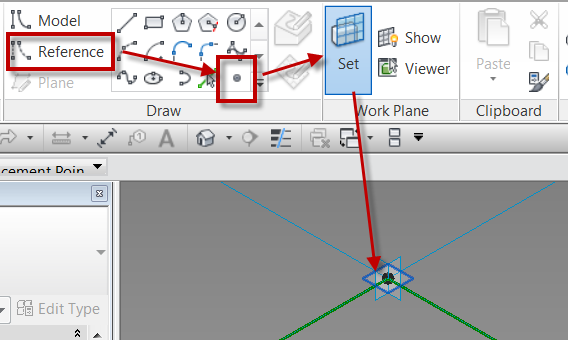
  2. Draw a point directly on top of adaptive point 2, making sure the Z work plane is used as the workplane
    • Start the Reference Point command
    • Use the Set Work Plane command
    • Tab to get the horizontal work plane on point
    •  Roof_Cricket_Rig_01
  3. Select the recently placed point
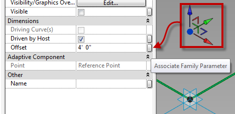
    • In properties change the “Offset” value
    • Select the “Associate Family Parameter” button
    • Create a new parameter named “Rise”, and make it instance based
    •  Roof_Cricket_Rig_02
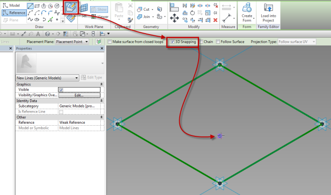
  4. Draw a reference line between the newly created point and adaptive point 4, making sure the Draw on Face selection is highlighted and 3D is checked in the options bar
    • Roof_Cricket_Rig_03
  5. Draw a reference line from adaptive point 1 to the new reference point
  6. Draw a reference line from adaptive point 3 to the new reference point
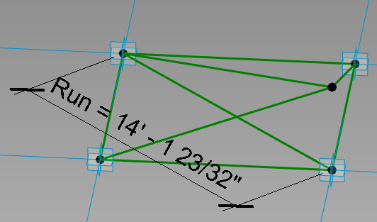
  7. Draw a reference line from adaptive point 2 to 4
  8. Set the work plane to be the horizontal plane of the diagonal reference line
  9. Place a dimension from adaptive point 2 to 4 (make sure adaptive points are being selected)
  10. Label the dimension with a new reporting parameter and call it “Run”
    • Roof_Cricket_Rig_04
  11. Open the Family Types dialog
  12. Create a new instance based length parameter, label it “Slope”
  13. Add the formula “(Slope*Run)/1”
    • Roof_Cricket_Rig_05
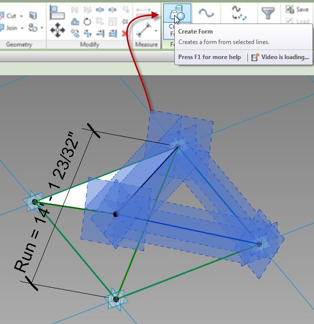
  14. Select three of the upper reference lines
    • Select the create form button
    • Select the surface option
    • Repeat for the other three upper reference lines
    • Roof_Cricket_Rig_06
  15. If desired, add a material parameter to the surfaces
  16. Save the file