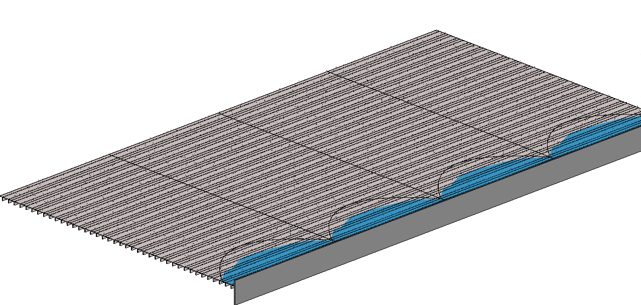
Dezi was working on a project where she had to figure out the amount of water that was accumulating in a failing double T. Of course she approached the problem as an engineer and incorporated a lot of math into the family. I decided that was something best left to an engineer and I decided to take advantage of that intelligence she had incorporated into the double T family and create an adaptive component to display the water graphically as well as extract volume from the family. It is hard to see in the picture but all of the double T’s are sagging and the adaptive “Water Volume” family is reacting to the as well as the depth of water.
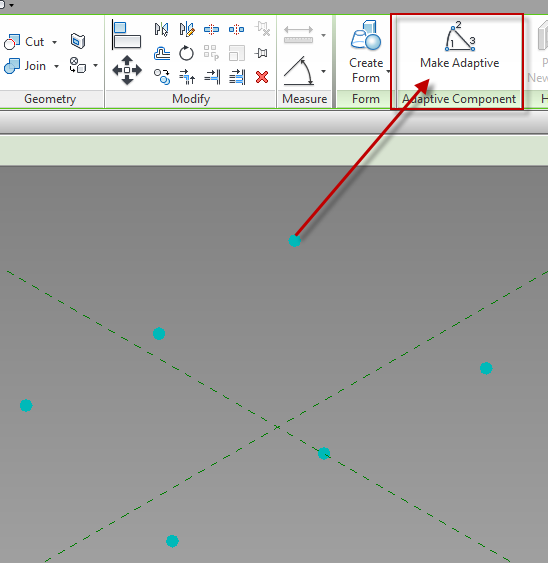
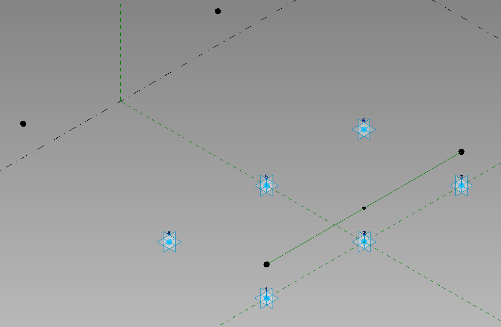
I started with a Generic Model Adaptive for this task. This family was going to be controlled by the ends and middle of 2 separate double T’s. I placed 6 reference points on the level. Once those are placed select them and change them to adaptive points.
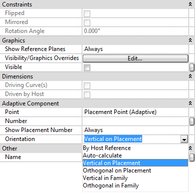
Once the points are made Adaptive new properties will be available. Orientation is a key value to pay attention to, in this case the points need to be changed to Vertical on Placement. If this is not selected then the form will be allowed to go any direction, we want this form to always be vertical.
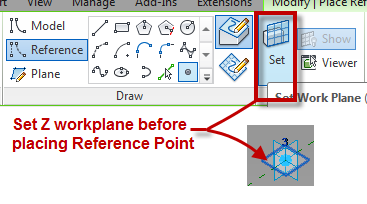
The second step was to host a reference point onto point 1 & 3. It is critical that the “Z” work plane for each point be set before the point to be hosted on it is placed. To do this use the Set Work Plane button then select the appropriate plane on the point.
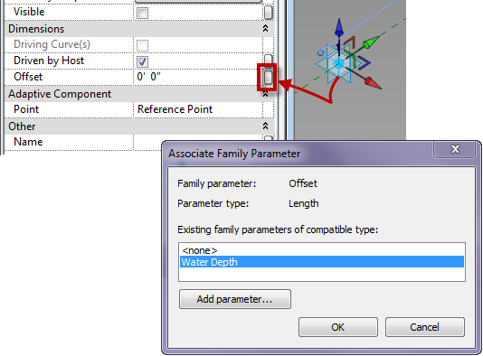
Once those points were created I mapped a parameter (Water Depth) to the offset value of the points.
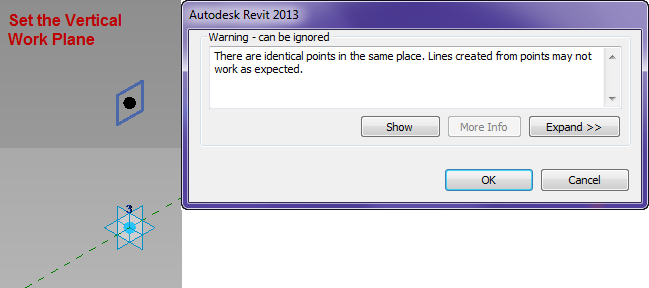
Next I associated a point to each of those points on their vertical work plane, clicking ok to the warning dialog.
I then mapped a parameter to the offset of those points. so that they will go back towards the other points. Next draw a reference line between the points hosted on adaptive 1&3, then place a reference point at the midpoint on the reference line.
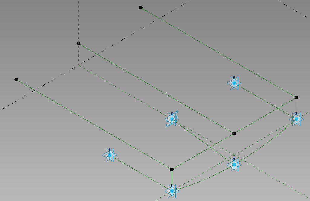
Host another point on the point hosted on the center of the reference line and associate a parameter to the offset value of this point. Then connect the points with Reference Lines (as per the image below), making sure 3D snapping is turned on. Draw a spline through points use the adaptive points 1,2 and 3.
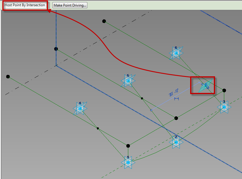
Move the adaptive points 4, 5 and 6 up vertically, then host points on the reference lines between the front and back adaptive points. Select these new points and pick host by intersection, and select the reference lines above.
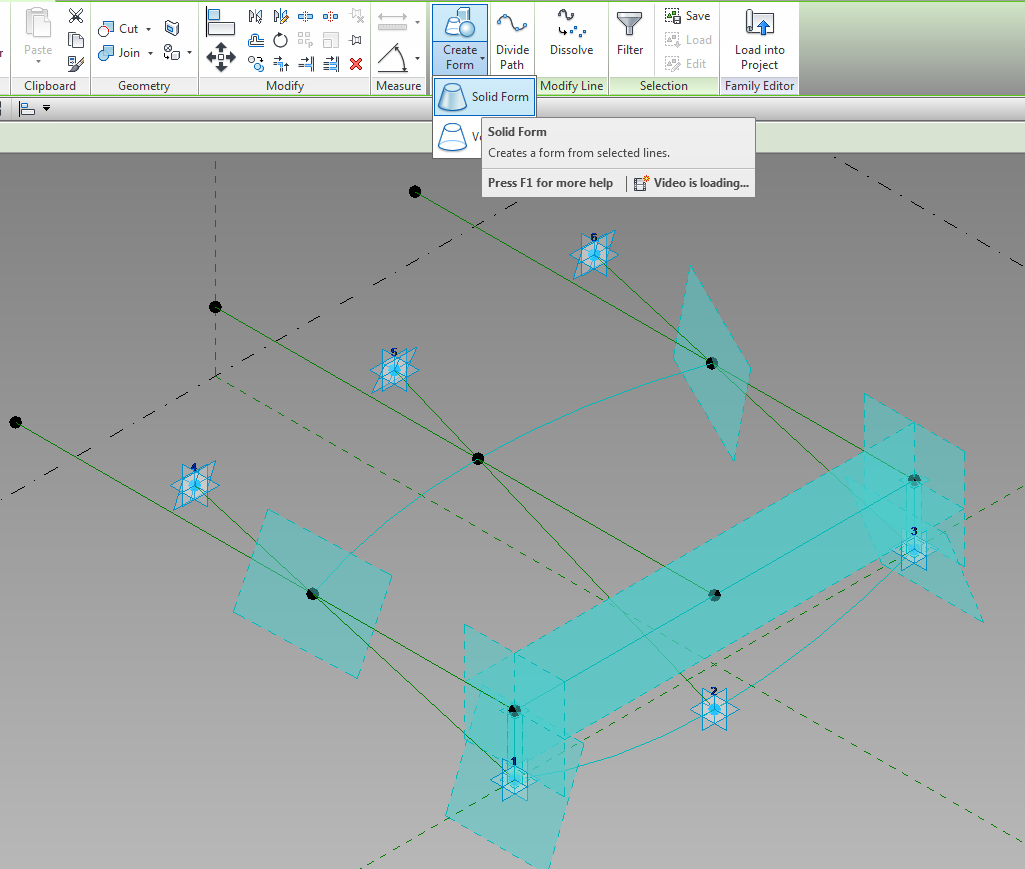
One those points are hosted by the intersections draw a spline through points from them. Then select the two spines, and three front reference planes and create a solid form from them.
Apply materials to the solid and it is ready to use.

