Tag Archives: Adaptive components

Non Rectangular Curtain Panels

As most Revit users have found a custom curtain panel family can only be rectangular in shape. Anything that becomes non-rectangular will be replaced with a system panel, either empty or solid, as seen in the image below.

I have used several workarounds in the past depending on the panel being used. This week I recently decided to use a common family type that I use to solve alot of Revit limitations and that is the use of an adaptive component family. What I realized is that even when a panel is changed to the Empty System Panel type there are still 6 faces to this invisible element. Which means we can snap to any of those surfaces or corners. Plus a System Panel Solid is then changed to an Empty panel they both have 6 surfaces. I used the default System Panel Solid to snap my adaptive panel to, then I changed it out to and Empty panel the adaptive point stayed. If the grid lines move in the curtain wall design the adaptive panels will adjust with the changes. The only disadvantage is each panel will have to be replace manually by placing all the points.

In order to make the tedious process of placing the points on the panels and selecting the correct points I created a system panel that had a ridiculous offset (mine was 150mm, 6″) and another with a different offset. I then changed the panel types to alternate offsets.

Not saying this would be an ideal situation for hundreds of panels but if there are only a few dozen then it is a decent alternative.

Adaptive Component – Everyday Uses part 5 Roof Cricket

Continued from..

Adaptive Component – Everyday Uses part 4
Adaptive Component – Everyday Uses Part 3
Adaptive Component – Everyday Uses part 2
Adaptive Component – Everyday Uses part 1

Roof Cricket Family

This section of the handout will give step by step instructions to create a variation on the roof cricket family.

  1. Start with the OOTB GenericModelPatternBased template
  2. Draw a point directly on top of adaptive point 2, making sure the Z work plane is used as the workplane
    • Start the Reference Point command
    • Use the Set Work Plane command
    • Tab to get the horizontal work plane on point
    •  Roof_Cricket_Rig_01
  3. Select the recently placed point
    • In properties change the “Offset” value
    • Select the “Associate Family Parameter” button
    • Create a new parameter named “Rise”, and make it instance based
    •  Roof_Cricket_Rig_02
  4. Draw a reference line between the newly created point and adaptive point 4, making sure the Draw on Face selection is highlighted and 3D is checked in the options bar
    • Roof_Cricket_Rig_03
  5. Draw a reference line from adaptive point 1 to the new reference point
  6. Draw a reference line from adaptive point 3 to the new reference point
  7. Draw a reference line from adaptive point 2 to 4
  8. Set the work plane to be the horizontal plane of the diagonal reference line
  9. Place a dimension from adaptive point 2 to 4 (make sure adaptive points are being selected)
  10. Label the dimension with a new reporting parameter and call it “Run”
    • Roof_Cricket_Rig_04
  11. Open the Family Types dialog
  12. Create a new instance based length parameter, label it “Slope”
  13. Add the formula “(Slope*Run)/1”
    • Roof_Cricket_Rig_05
  14. Select three of the upper reference lines
    • Select the create form button
    • Select the surface option
    • Repeat for the other three upper reference lines
    • Roof_Cricket_Rig_06
  15. If desired, add a material parameter to the surfaces
  16. Save the file


Adaptive Component – Everyday Uses part 4

Continued from..

Adaptive Component – Everyday Uses part 3
Adaptive Component – Everyday Uses part 2
Adaptive Component – Everyday Uses part 1
 

Nesting Families

When creating families it is sometimes necessary to nest other families, and this is more common with adaptive families.  However, not all family types can be used with adaptive families. For example profiles, structural columns, or beams cannot be loaded into an adaptive family.  If a nested profile is needed, then a generic model family with model lines, either adaptive or not, can be used in lieu of a profile family.

A great family to consider nesting, especially when adaptive families are a new to the user, is the out-of-the-box “Diagnostic Tripod” family.  This family will display how the adaptive family is working once it is loaded into another family or project.

Repeaters and Divisions

If a family is going to be repeated, which is similar to an array, then nesting families is a must, as is using a divided path or surface.  The first step is to create a division from either a surface or a line.  To do this, select the element and use the Divide Path or Divide Surface command.  Since the 2013 products, a series of lines may be selected and divided as a single element.

DividePath

A divided path also has properties that will allow for a beginning or end indent.  These properties give further adjustment to the location of the hosted elements.

If a nested family will become a repeater, it will have to be an adaptive family.  To create this, first place the family on a point, or series of points, that was created from the division tool.  When doing this, make sure to select the node that was created by the division.  Next select the element and use the Repeat command (same button as array in a normal family or project).

Bolts_Repeat

Up next…

Adaptive Component – Everyday Uses part 5

Adaptive Component – Everyday Uses part 3

Continued from..

Adaptive Component – Everyday Uses part 2
Adaptive Component – Everyday Uses part 1

Creating Forms

Unlike the normal family editor, in adaptive and mass families, surfaces and solids can be created.  These are created using the Create Form button and not extrusions, sweeps, etc..  Unfortunately points cannot be used to create elements, reference lines and/or model lines must be used for this task.  Lines can be used if they are part of the rig, however, if additional lines are required, then they need to be created prior to creating solids or surfaces.  In the adaptive (as well as mass) family environment, surfaces can be created from a single line or from multiple lines.

Surfaces and Extrusions

To create a solid or surface, select the desired lines and select the Create Form button.  Voids can be created in the same manner.  If Revit can determine more than one way to create a solid, or if it can create a surface, different images will appear on the screen allowing a user to select the appropriate one.

CreateForm

Sweeps

A sweep is created by drawing lines for the shape of the sweep, then by selecting those and the lines that represent the path.  Once all of the elements are selected, use the create form button to create the sweep.

CreateForm_Sweep

Revolves

A Revolve is created by selecting a group of lines or arcs that are all parallel to a single line.  This one line acts as an axis.

CreateForm_Revolve

Once surfaces or solids have been created, their faces and edges can be used to generate additional forms.  For example, the edges of a cube can then be used for the path of a sweep, or the edge of a surface can be used to generate an additional surface.

Up next…

Adaptive Component – Everyday Uses part 4


Adaptive Component – Everyday Uses part 2

continued from Adaptive Component – Everyday Uses part 1

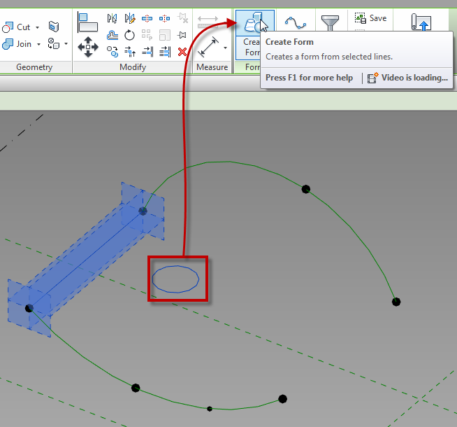
Creating the Family Rig

Adaptive families consist of elements, most of which are different than the normal family environment.  These elements will include: reference points, adaptive points, shape handle points, reference lines, surfaces and solids, all of which will be discussed in further sections.

Points

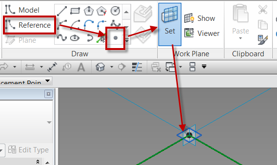
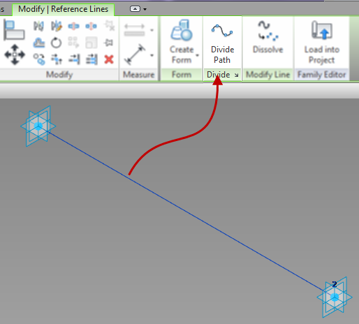
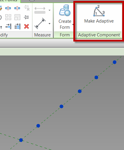
Adaptive families use adaptive points, however there isn’t an adaptive point drawing tool.  In order to create adaptive points, reference points must be placed and then made adaptive.

To create an adaptive point simply place a reference point, select the recently placed point(s) on screen and choose the Make Adaptive button on the contextual ribbon.  Alternatively, a point can be selected and this value can be changed in the properties dialog.

Adaptive_Points

Adaptive_Points_Numbered


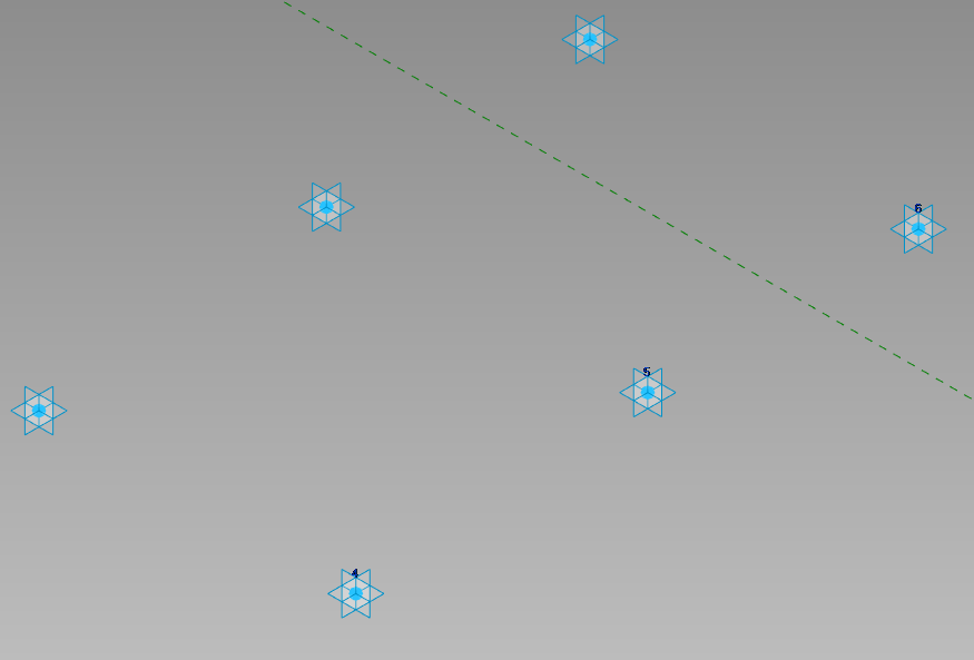
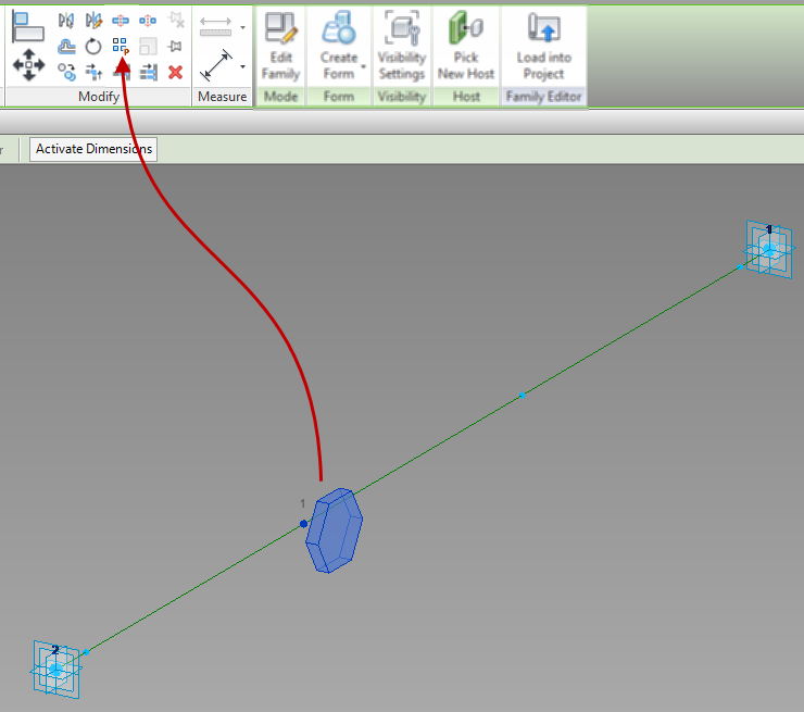
Once points are made adaptive, the local x, y, and z planes of each point will become visible.  These planes are then all available to be used as references.  The adaptive point numbers will also be displayed in the order in which they were created.  If the numbers need to change, select the number above the point and change the value.

Reference points are a different type of point.  Reference points are usually hosted on another object – a reference line, adaptive point, or another reference point.  Reference points also have work planes that can be used to assist in the modeling process, although they are not displayed by default.  If it is the desire to display the work planes, this can be adjusted in the properties on a point by point basis.  Points will also vary in size on the screen based on whether or not the point is hosted.

Driving points are points that control the nodes of a spline or arc.  They can be recognized by their value of Drives Curve(s) in the properties.

Lines, Splines, Arcs and Circles

In the massing and adaptive family environment there are 2 types of lines that can be created, reference lines and model lines.  Both of these elements are created the in the same manner and work in similar ways, however there are a few subtle differences between them.  Model lines do not have any work planes associated to them, however they can host points.  Model lines get absorbed into the surface or solid they were used to create.  Reference lines have four work planes, one on each end, and one in the X and Y direction.  Any curved reference line (i.e. splines, circles and arcs) only have work planes associated with the end points.  Unlike model lines, reference lines remain when used to create solids or surfaces.  These line types can easily be changed from reference to model by simply checking the “Is Reference Line” in the properties dialog.

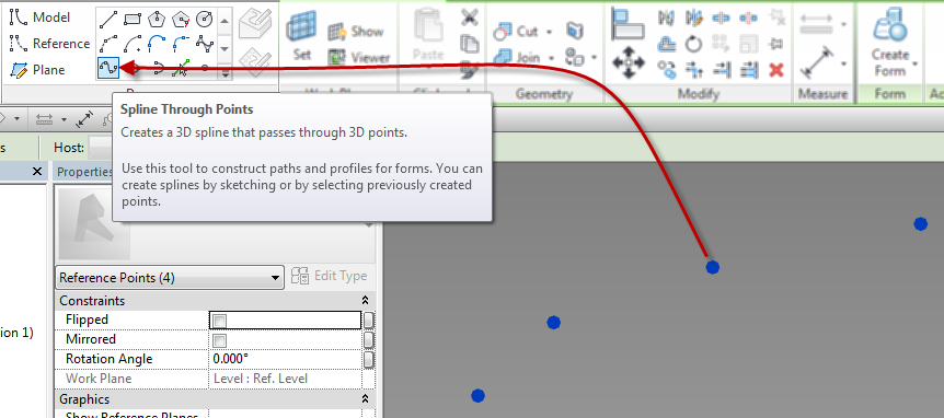
Splines and Lines by Points

When creating lines and splines, there is an option to create both of them directly by clicking on the screen, however both of these can also be created by selecting previously created points.

  • For splines this can be accomplished two ways, either select the spline by points tool and click on the screen for the spline vertices, or select already drawn points and then click the spline by points tool. If the spline is created by selecting points, it will always create a model line; if a reference line is the goal, change the value in the properties of the line.
  • SplineThroughPoints
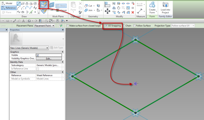
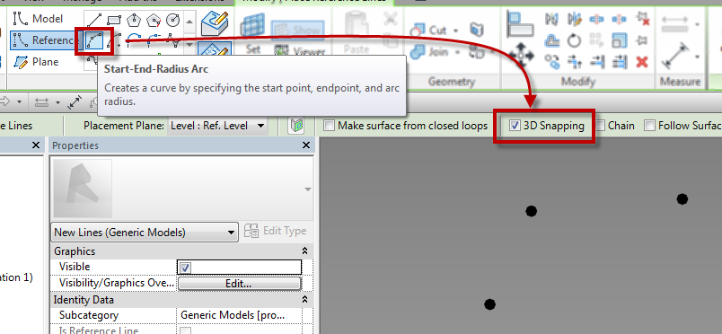
  • The capability to draw an arc through points is a relatively new feature. This tool only allows for the arc to be drawn on screen from previously created points. In order for this tool to work properly, the 3D snapping check box must be enabled prior to picking the points that are going to create the arc.
  • ArcThroughPoints

Hosted Points

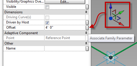
By default, when reference points are placed they are hosted on an element, which can be a level, plane, line, or surface.  Properties will vary depending on which element is the host.

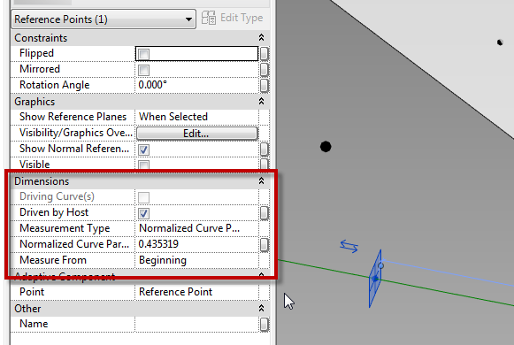
  • Points hosted on a line will have “Measurement Type” as a property.
  • HostedPoint_Line
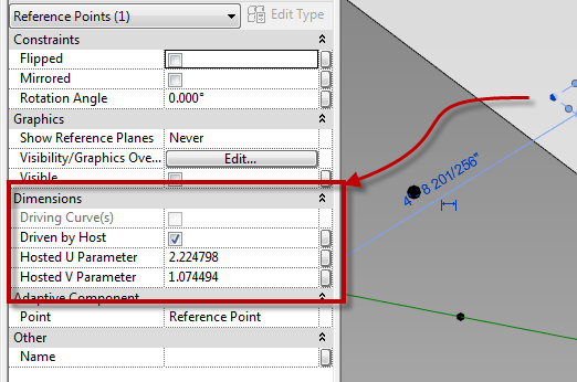
  • Points hosted on a surface will have “Hosted U & V Parameter” as a property
  • HostedPoint_Surface
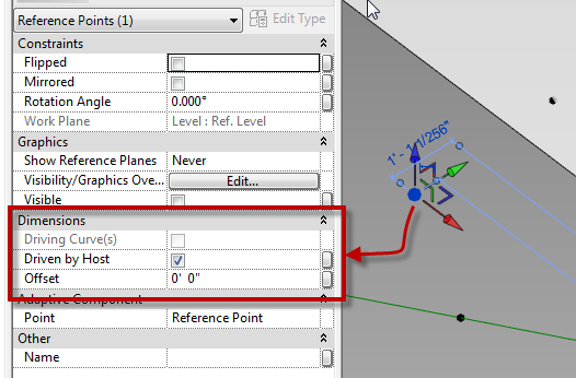
  • Points hosted on a reference plane, reference level or another point will have “Offset” as a property
  • HostedPoint_ReferencePlane

Knowing these values and how to take advantage of them will become critical when working with adaptive families.  All of the above properties can have associated parameters to help further the development of the family.  Points hosted on lines have the value of “Measurement Type” which also has additional options that need to be considered, and these options will vary depending on if the point is hosted on a straight or curved line.

  • Non-Normalized Curve Parameter = Radians when on an arc or circle (not useful when using straight lines)
  • Normalized Curve Parameter = ratio of the arc length of the arc or line from 0.0 to 1.0
  • Segment Length = Length of the point from either the beginning or end
  • Normalized Segment Length = Ratio of the length of the line from 0.0 to 1.0 (same as normalized  curve parameter for lines and arcs different for splines)
  • Chord Length = Direct distance from the begging of the line, arc, or spline to the point
  • Angle = Angle from the beginning of the arc or circle to the point (arcs and circles only)