Category Archives: Architecture

Revit Architecture topics

Revit Railing Support Bug 2

As I am preparing to teach another session on Revit Railings I noticed another small quirk.  Again in this example I am using railing supports to act as balusters, a great option when dealing with glass panel.

In this image I have a support to look like gasketing material as well as glass supports, these are associated to the U track handrail.  This allows for the glass seam to be unpinned and moved to any desired location.

Railing Support Quirk 01

The quirk arises when the handrail has a value for a fillet radius, even though the Default Join is set to Miter.  If the support is unpinned and moved it will move along the radius as if the value were set to Fillet no Miter.

Railing Support Quirk 02

Revit Railing Support Bug

I have been teaching and using the hack to use railing supports in leiu of baluster or to use them for gates etc.  Yesterday a client told be about an issue with Railing Supports, they do not abide by phasing graphic overrides.  In cases where the supports are simple brackets (as shown below this probably isn’t that big of a deal.

Railing Support Phasing Issue 0

However when you are utilizing support for balusters or for gates (as shown in the two images below) this becomes a big issue.  This has been reported to Autodesk and I was able to reproduce the issue in both Revit 2017 & 2016, I didn’t test it in older versions of Revit.

Railing Support Phasing Issue 1

Railing Support Phasing Issue 2

Room Awareness

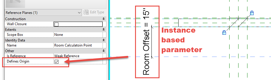
Paul Aubin and I were having a discussion the other night about signage.  It made me think of an age old process (age old for me at least) that I have been using since the early days of Revit and I thought I should share it.  When placing signage on a corridor wall it would be nice to have the sign be able to pick up a room id from a given distance on the other side of the wall.  As you may know that when scheduling an object it does know what space or room it is located in.  In this example the sign would know it was in the corridor and not represent the room or space it is intended for.  Families know their location in Revit by their insertion point, with hosted families the insertion point doesn’t have to be the face of the host.  I know this sounds odd but the family will host to the face, but the reference plane that defines it’s insertion may be in front of or behind the host and that is the value Revit will see to report the Room it is located in.  Yes Revit did introduce the “Room Calculation Point” tool in the family editor, but since it only goes a single direction and the distances aren’t adjustable it, in my opinion, is completely useless to me.

My solution was to add a reference plane behind the host surface (in this example the Host Back Face) and give that reference plane an instanced based parameter and set the “Is Reference” to weak and make sure the “Defines Origin” is selected.  This way I can now drag the reference plane such that it is inside the room that I need the sign to schedule.

Signage Insertion Point

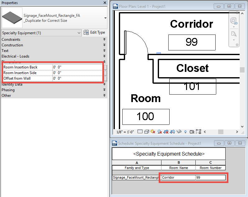
In the project example below I have also added a side offset such that I can place the signage in the corridor and get it to read any of the room data behind the wall.

This example has all the insertion points set to 0″ and it will read the Corridor.

Signage Insertion 0


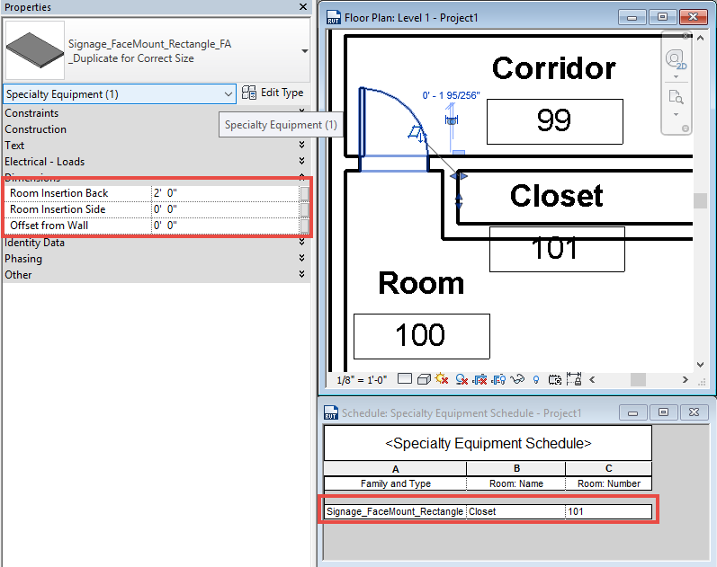
This example I was able to drag the insertion point (Room Insertion Back Value) to get it to register the Closet

Signage Insertion Back

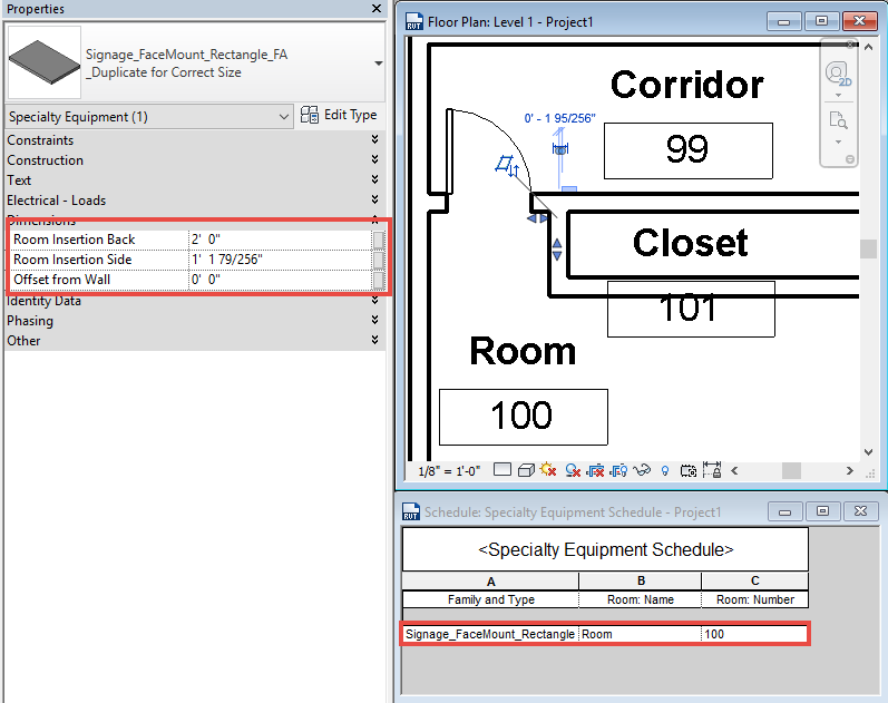
Then adjusting the Room Insertion Side value I can get it to schedule as Room 100

Signage Insertion Side

If you didn’t know about this trick hopefully it will inspire you to use it in other ways

Wall Vertical Structure Grayed Out

While assisting a client I was showing them how to create a vertically compound wall the only tools available to me where Sweeps and Reveals.  Modify, Merge Regions, Assign Layers and Split Region were grayed out.  I had the section preview active in the dialog so this wasn’t the issue.

Camera View Limitation 1

I usually modify families by selecting them in the Project Browser and not selecting them on the screen.  In this case this was my downfall, I hadn’t noticed that amongst all the tiled views on the screen the active one was a camera (perspective) view.  A well known fact is that there are many limitations while having a camera view active.  For instance having a camera view active will limit the capability to activate a Revit Addin or Extension.  Having access to only a couple of the vertical structure modification tools was a new one to me.

Align Eaves

During a recent session of Revit Radio I was asked a few questions about roofs and their properties.  A post I did a while ago on Roof Overhang Values which covered one of the questions.  However it didn’t answer the question of why are the roof eaves not aligning? In the image below both sides of the roof have a 3′ (914mm) overhang with the same roof pitch on the entire roof.

Align Eve Plan

The reason this may happen is the fact that one of the sketch lines used the pick wall tool whilst the other was simply drawn as a line (or possibly the pick lines tool with an offset).

What the help file doesn’t explain is that when the pick walls tool is used along with defining that edge as a slope then the slope starts from an edge of the wall picked (the edge of the wall depends on if Extend into Core is used or the roof is set as a Truss or Rafter).  If a line is sketched then the slope will start from sketch line itself.  Using both of these tools will cause the issue as seen in the above image.  Revit however does have a simple tool to assist in adjusting the roof eaves if this situation does arrive.  The tool to accomplish this task is Align Eaves and can only be accessed while in sketch mode.

Align Eaves

If the eaves are aligned Revit will flag a warning of “All eaves are already aligned”, if the eaves do not align then Revit will display the elevation of the eaves relative to the closest level.  There are also two overlooked option on the contextual ribbon “Adjust Overhang” & “Adjust Height”.  Before attempting to adjust the eaves make sure to select the correct option, most of the time this will be Adjust Height, yet the default is Adjust Overhang.  Once the correction option is selected choose the value that is correct and select the sketch lines that need to adjust, similar to the align tool.