Category Archives: Architecture

Revit Architecture topics

Adaptive slab edge

While training a client today the question had come up of how do you do a slab edge when the slab isn’t flat?  This can always be done as an inplace family sweep with a defined profile, but as we all know to many in-place families have a tendency to slow Revit down.  So we went through the process of creating an adaptive family.  The only complaint I have is the limited categories that adaptive components can be, so in this case we left it as a generic model so that it can host rebar.

Start with the Generic Model Adaptive  template, then change the category if desired, we left ours as a generic model. 

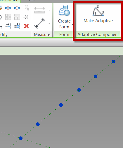
Place ref-points as needed in the view, select the ref-points and change them to adaptive in the contextual ribbon.

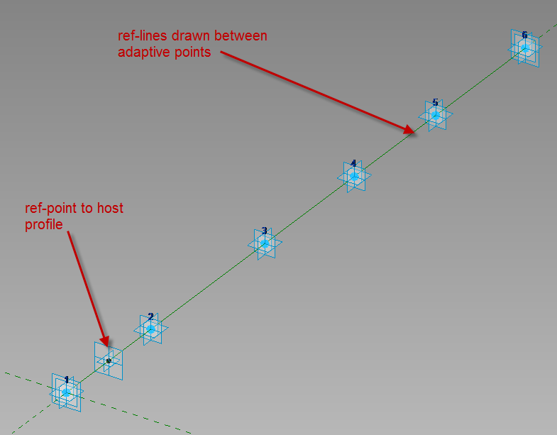
Draw ref lines from the first adaptive point to the second to the third etc., make sure 3D Snapping is on before drawing.  Next draw one ref-point on the ref-line, this point will be used to host the profile.

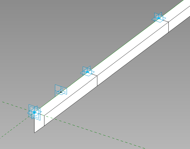
Since profile families can’t be used inside of an adaptive family create a generic model using model lines to be the profile of the thickened slab, load that into the family and place it on the ref-point.  Select the profile family and map the parameters to parameters in the adaptive family.  Select the profile and the ref-lines then create form.

This is what we had come up with instead of in-place families.  Comment if this works for you or not.


Stucture Generator

I thought it would be fun to create a simple radio tower for Revit Radio and in doing this I figured the Structure Generator preview from Autodesk Labs would be a good tool to try out.  The Structure Generator is a preview tool for both Revit Architecture and Structure that allows structural components to be generated in a project from conceptual masses.  Here is the official quote from Labs…

“Project Structure Generator for Autodesk® Revit® Structure and Autodesk® Revit® Architecture software is a free* technology preview that provides a connection between massing models and objects created during conceptual design and structural elements such as beams, column, walls, plates. With Project Structure Generator, structural engineers and architects, from the earliest stages, can very quickly create and visualize a physical and analytical model of a structure based on the massing model.”

 It was a bit rough of a go around just jumping into the program but once the help file it brought up it helps describe the processes to get this tool to work.  I first started off with a tall box and ran the tool using all the default settings.   I always like to start a tool with the default setting to see how well it works before I start breaking it. This was not that successful, Dezi asked why I was modeling a paper bag?

Continue reading

Continuous Overhanging Gable Roof

A question came up in the Linkd In Group for Club Revit  about creating a single roof with a gable end that would basically go underneath itself to attach back to a wall.  I thought I would do a post to my simple response, so that I can get a bit more detailed in the explanation.

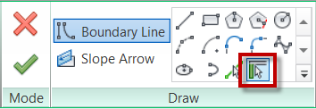
The first step is to create a roof by footprint, personally I would use the Pick Walls tool for this situation.  Uncheck the defines slope option to get the gable ends as needed.  Finish the roof when done


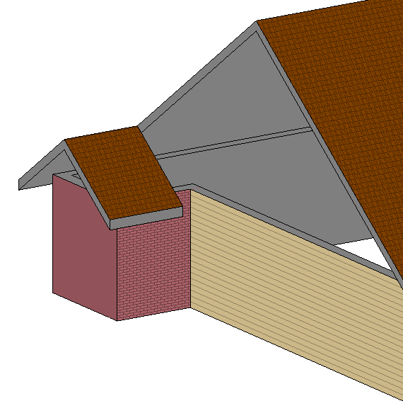
This doesn’t alone dosen’t get the small gable end roof to come back under itself to attach to the wall.  It also doesn’t automatically take the walls up to the roof.


I chose to model another wall above the other and make it the full length of the roof, and then attach that wall to the roof.  This way I have something to Join the roof to.


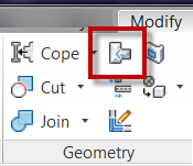
The next step is to use the Roof Join/Unjoin command located on the Geometry panel of the Modify Tab on the ribbon.


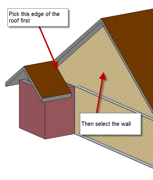
Pick on the edge of the roof that needs to Join to the wall and then pick on the wall.


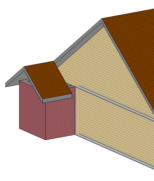
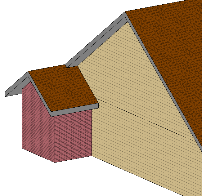
This will be the completed result.  Now just go in and add all the detail like soffits, fascias and gutters.


Show Walls Below Roof

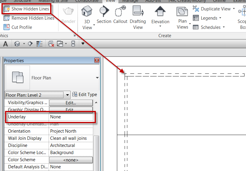
After my post about show hidden lines someone had contacted me and had a concern that this tool didn’t work for what he needed.  In this particular case the person was talking about showing walls below the roof.  He had went through and used the show hidden lines tool and some of the walls displayed hidden while other didn’t.  The underlay value had been set to display the floor below the roof, some of the walls remained half-toned and others displayed hidden. Once the underlay was turned off (see note below on underlay) the walls that weren’t showing hidden disappeared.  In this case there were actually different issues that were causing the walls not to display hidden.  One of the issues was with the view range settings.  The view range bottom and depth were set to to current level at 0″ so that nothing below the view could be seen, so once the underlay was removed the hidden lines didn’t display.   The view range was changed to be -1″ below the current level, for both the depth and bottom, and then the hidden lines appeared.  The other issue was the fact that some of the walls had been attached to the roof, this allowed the show hidden lines to work with out adusting the view range.

NOTE: Underlay displays another slice of the model under the current plan view. That slice of the model can be from above or below the current level. The underlay appears dimmed and is visible even in hidden line visual style.  The orientation can either be a Plan or RCP .

Quick floor sketching method

About a year ago I read a blog that talked about using ceilings as floors in order to utilize the easy auto sketch option with ceilings.  Most of the time I disagree with using tools for things that which they aren’t meant, assuming there is a simple way to use the correct tool.  That post, however, did get me thinking…

Quick side note: Normally when I explain any sketch tool in Revit I stress that using Pick Walls (or Pick Supports) associates the edge of a sketch to a wall (or structural framing member) such that if the wall moves the skethed element also moves.  However, the pick wall tool will only allow a user to pick one wall face, what if the floor is a finish floor, and the sketch lines need to be on each side of the wall.

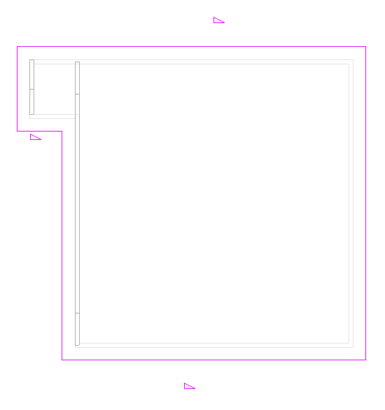
… when skething a ceiling, there is an “Auto Ceiling” command.  This tool allows a user to pick within a boundary of walls to create all of the sketch lines.  The sketch lines become associated to the walls, similar to “Pick Wall”, such that if the wall moves, the ceiling adjusts with the wall.  I, along with numerous others, have complained for years that there should be an option like this for floors.  When reading that post I thought, what if I copied the sketch lines to the clipboard from an existing ceiling and pasted them into the sketch mode of a floor?  I tried this method, and it worked.  However, there was an issue that kept occuring, which was a circular chain of references.  Somehow when using this copy and paste method the floor occasionally linked itself to the ceiling, so I couldn’t edit or delete one with out it affecting the other.  Feeling slightly defeated, but not ready to throw in the towel, I tried a similar method, but started by creating a new ceiling and then copied the “Auto Ceiling” sketch lines to the clipboard, cancelled the ceiling command, and then used Paste “Align to Current View” to paste the sketch lines into the sketch mode of a floor.  Once I used this approach, the  circular chain of references was no longer an issue.  This method works great for finish floors, as well as slab on grade, where walls need to pass through the slab.