As I am setting up my new template for 2013 I will be posting all the little quirks I find so everyone doesn’t have to bang their head on the keyboard as I am doing.
At first glance these tools look great, however once you get into the nuts and bolts of them you will find many different quirks. Today’s quirk is with the Handrail Type and Top Rail and how they display, or how they don’t display. One of the values both of these have in common is the capability to have a fillet radius at all the joints. A really nice feature for this release, however the plan views don’t display them, unless the views’ detail level is set to Fine. Note this is only for PLAN views, all other views display them correctly.
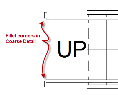
Be cautious however, because sometimes the top rail will disappear when these are adjusted. I haven’t found the exact reason why this happens, I am still digging into this issue.
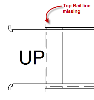
I don’t want all of my plan views to display in fine so I wanted to show a Visibility Graphics tip to everyone. The far right column of the Visibility Graphics dialog box allows for an individual category to be set as desired. For Rails in 2013 I have set this to be Fine so that all fillets will be displayed in plan views.

I also am puzzled at the inconsistency of when rails above are being displayed. In the image below you can see in the inside handrail is displayed all the way up the stair, however the outside rail disappears at the landing.
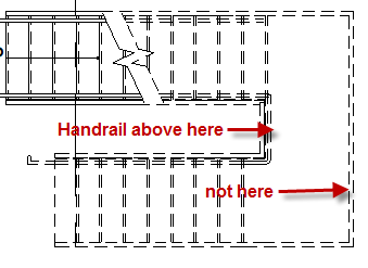
If anyone has a solution to any of these quirks please comment and let myself and the world know.



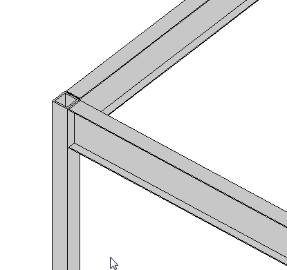 If you have a a beam connected to a column, similar to what is shown (element types can vary), there is a value in the instance properties of the beam called “Start/End Attachment Type”. This property can be changed to End Elevation or Distance, by default the value is End Elevation. End Elevation maintains the value of the beam to the placement level and Distance orients the value to the join location on a column. So if you are wanting the beams to move up and down with the top (or bottom) of a column then you simply change this value to Distance.
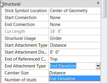 Once the value is changed to Distance then you will see two new properties show up for the beam, “Attachment Distance” and “End of Referenced Column”. Attachment Distance option allows a user to put in a value for an offset of the beam to the top of the column, so that the beam will still move up and down with the column just be that given value away. End of… allows the beam to be either associated to the Top or Bottom of the column.