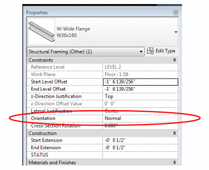
This is one of those Revit basics that has been forgotten, or perhaps never learned. In the instance parameters for structural framing members, there is a parameter called “Orientation”.
The framing member is only affected by this property if it was modeled on a sloped work plane.
The default orientation is normal – normal to the work plane.
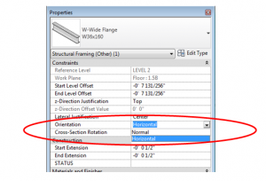
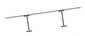 If the orientation is changed to horizontal, the beam will rotate such that the flanges are horizontal.
One item of note is that the rotation point is at the intersection of the top of the beam and the lateral justification (Side 1, Center, or Side 2), so if perfect accuracy is required, the beam may have to be shifted down. The screen shot below shows how the different combinations of a horizontal orientation interacts with the Lateral Justification.

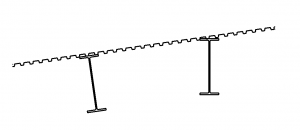
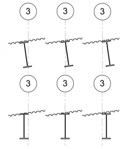
When using normal orientation it can be very challenging to dimension to the correct location line of the framing. I don’t like the way this feature behaves.
I agree; I struggle with this sometimes too. Perhaps Autodesk will work on this someday.
Dezi, this helped when Autodesk wiki was down. I couldn’t recall how I’d rotated outriggers for an arched feature. You helped me remember I’d created a sloped plane, placed the element on the plane, then worked from there, deleting the plane along the way.
One bug to watch is Revit’s prediliction to re-assign the object to a level if you delete the work plane without first detaching from the work plane. That almost jammed up my progress.
There are times where I don’t comprehend why Revit programmers insist on certain conventions and this is one of them.
Thanks for the reminder.