Category Archives: Platform

Analytical Model

In preparation for my session on Structural Tools for Architects at BIM Workshops in Anaheim I thought of a nice tip that would be a good blog post.  When discussing structural tools inside of Revit I have heard the comment a few times that the model slows down once structural members are added.  If the members being added are K series joists or something similar then it could be due to heavy families.  Never the less what is also adding to the speed issue is the fact that all structural member, by default, have analytical properties attached to them.  Unless your firm exports out the structural members to an analytical program this feature isn’t needed.  To resolve this issue after the model has been created select all structural columns, beams, foundations etc and uncheck “Enable Analytical Model”.  If this is unchecked before placing an element that setting will be remembered and any element placed after, thus eliminating the need to keep unchecking as the model develops.

Enable_Analytical

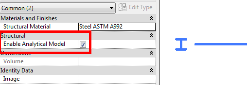
The real tip here is to open your company template place a structural column, beam, brace, floor, wall and all three foundation types, before placing each type uncheck the “Enable Analytical Model” then delete the elements.  Your template has now been set to not have analytical model enabled thus possibly speeding up future models.  The only nuance is any member as part of a beam system or truss will still have the analytical model associated to it.

Revision tags rotate with component

The other day while in training I found a subtle nuance to revision tags. If rotate with component is checked then the tag rotates with the curve of each bubble.  I know this option only works with draw type elements such as walls, beams, footings etc. (See Steve’s posts older, newer). I thought this was new to 2015 but found out it goes back a few releases. I am not sure why a firm would want the tags to be printed at varying angles but this option is available.

RotatesWithComponent

Sizing Reference Planes

I was doing some work with The Ant Group doing some detail work when Jim Balding (JB) mentioned a tip that I can’t believe I hadn’t been using for years.  When I create family content I am very specific about making sure the reference planes aren’t longer than needed, centered in the family etc., especially when working with detail components or generic annotations and tags.  I have family templates for most family types, my detailing template has been set such that the reference planes are centered, equal length and around 4″ (100mm) in length.  When I start a family from this template on of the first things I do is unpin the reference planes and stretch each end to the desired length for that component.  JB asked why I didn’t use the scale command?  He showed how he uses scale by selecting the reference plane(s) and scaling it from the center point, clicking the end then clicking again at the desired final length.  This really is a great tip when both of the reference planes need to be sized equally.


Windows Explorer/My Computer Columns

I previously posted about how to use the windows column filter to display what is needed.  I thought there should be a follow up post on how to change the display of the columns as well.  If you right click on a column header there will be a context menu that comes up allowing for a few options.  One I use often is Size All Columns to Fit, depending on what I am looking for sometimes I will select the More… option and add additional columns to see properties that are otherwise not visible.  Plus I have been in the habit of adding tags, titles etc when in Word or Excel, this way I can sort by these values in Windows Explorer.

Windows_Explorer_Columns

Vertical Face Based Template

I had mentioned this tip to a bunch of speakers at the BIM Workshops and they had never heard of this so I figured it should be a post, especially since one of them came up and gave me a kiss on the cheek.

When creating face based families the biggest complaint I hear is the fact that if the element is going to be placed on a vertical face, in the family the front is the plan view.  I agree this can be confusing, so why not create a vertical face based template instead of using the OOTB horizontal face based template.  Impossible you might think, well up until a year ago I thought so too, until  I learned about a workaround on changing a wall, ceiling or floor based family to a face based family from our local user group (RoMBIS).  Note you will have to have Revit MEP or Revit for this tip to work, if you have Revit Architecture or Revit Structure then you will have to download my version.  The thing I noticed when using this tool is that if I converted a Wall Based element then the surface it uses as the face is vertical.  This is when I decided to use these steps to create my own Vertical face based family.  I haven’t tried but I am sure the same thing could be achieved for an upside down face if a ceiling hosted family was converted.  However I will save all my readers the headache and post the file for download for everyone to use.

FaceBasedVertical

Here is the BD Mackey Face Based Vertical Template, there is an additional reference plane “Actual Face” as well as a parameter “Offset from Surface”, as I always build in a face offset for my hosted families.