With beam members there has always been the ability to show a start or end connection symbols. In the early releases connection symbols were limited to Moment Frame and Cantilever Moment. These symbols could have any graphics desired, but they were the only two options. In the last few releases this feature was opened up so many connection types and custom symbols can be created. Several firms have used this feature, but since it has been opened up, the applications can go beyond the classic option. Firms could use this feature for all types of building construction. For example, it could be used in wood construction to show the different types of hangers and/or fasteners in plan graphics. Customizing this feature is a multistep process, but once added to a template, the options will be available for the entire team to use.
- The first step is to create the connections symbols. There isn’t a template specifically designed for this, so start with a generic annotation family. Then, using the Family Category and Parameter button, change the family type to be Connection Symbol. The intersection of Reference Planes is the insertion point, which is the end of the beam. The symbol should be drawn to the right of the insertion point. There is also an option for “Automatic Cutback for Beams and Braces”. This option allows the symbol to add an additional cutback to the beam’s symbolic line in the project. If the intent is to have the symbol be added directly to the beam line, this should be unchecked.
- Once the symbol is created, load the family into the project, or project template. In Structural Settings, go to the Symbolic Representation Settings tab and add a new Connection Symbol for Breams and Braces. Once the new Connection Type is created, choose the appropriate symbol.
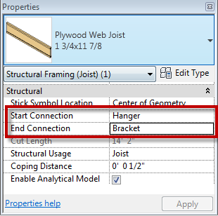
- Now when a beam is created the new options will be available for connections within the beam instance properties.
All of the above is also applicable to structural columns connections.


