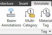
When using the beam annotation (Annotate tab, shown below) tool to quickly tag many structural framing elements, there are a couple quick tips that are good to remember.
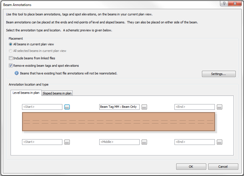
First, note that there are two tabs: one for level beams and one for sloped beams, see the image below. In all honesty, I cannot think of too many situations where one would want completely different tags on level versus sloped beams, but the option is there. So, if this tool is used and tags don’t show up, check that the correct tab was utilized. Also note that if a tag is assigned to a level beam and then later that beam is sloped (or vice versa), the tag will remain the same.
The other items to note are under the “Placement” options in the dialog shown above. There are several options available, so make sure to select the appropriate one, otherwise tags can be overwritten, missed, etc.

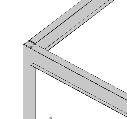 If you have a a beam connected to a column, similar to what is shown (element types can vary), there is a value in the instance properties of the beam called “Start/End Attachment Type”. This property can be changed to End Elevation or Distance, by default the value is End Elevation. End Elevation maintains the value of the beam to the placement level and Distance orients the value to the join location on a column. So if you are wanting the beams to move up and down with the top (or bottom) of a column then you simply change this value to Distance.
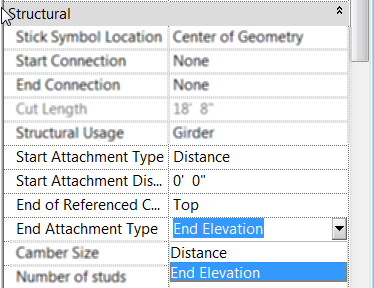 Once the value is changed to Distance then you will see two new properties show up for the beam, “Attachment Distance” and “End of Referenced Column”. Attachment Distance option allows a user to put in a value for an offset of the beam to the top of the column, so that the beam will still move up and down with the column just be that given value away. End of… allows the beam to be either associated to the Top or Bottom of the column.