Tag Archives: Structural Beam

Revit 2015 R2 Structural Framing Quirk

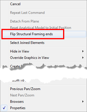
With the release of Revit 2015 R2 one of the big features for structural engineers was the capability to flip framing members.  A simple right click on the member and the option to “Flip Structural Framing Ends” appears.  This was a welcome addition and a nice feature to have, but be careful, there are some quirks involved with this feature.  This feature is in reality rotating the beam 180degrees while keeping some of it’s properties relative to the end and others not.

Revit_2015R2_StructuralFraming_Flip_03

Here are some of the quirks I have found to be associated with this new feature.

  • If one end of the beam is utilizing the “Attachment” value it will either be flipped or removed
  • Face based objects hosted to the beam will rotate with the beam and end up on the other side of the beam
  • Adaptive components hosted to the beam will either be rotated or simply disappear
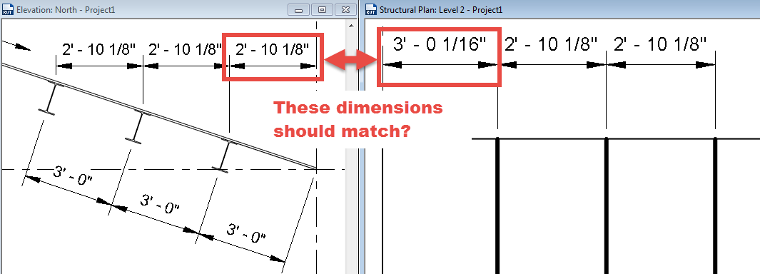
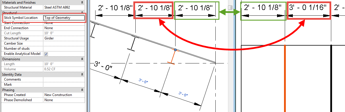
  • When flipping sloped beams they can become detached from their work plane (not like this warning is rare)
  • Cross section rotation will become a negative value keeping it’s relation to vertical (nice catch programmers)

In the images below the plate that host the clevis and rod is the OOTB gusset plate family which is a faced based element, the red connection plate at the top is an adaptive component family.

Revit_2015R2_StructuralFraming_Flip_01

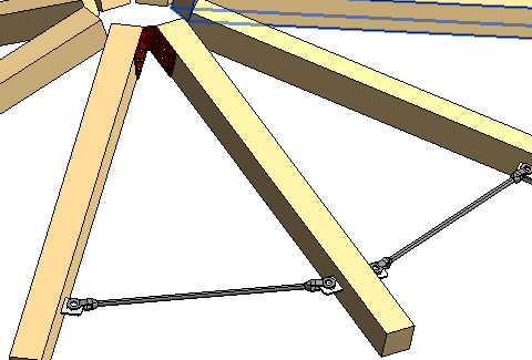
As you can see in the image below the beam rotates when flipped thus creating havoc on elements that are hosted to it.

Revit_2015R2_StructuralFraming_Flip_02

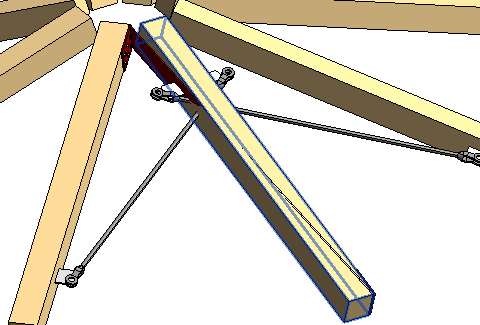
Conclusion to this feature is to be careful when flipping beams and verify elements aren’t hosted to them.

Dimensioning Sloped Framing

I have had some questions come up about dimensioning sloped framing, so I thought it deserved a blog post.

Question: Why can’t I dimension to framing members when they are associated to a sloped work plane?

  • This question comes up when attempting to dimension in plan, in a coarse level of detail, when the framing member is Normal to the work plane, and when using the Linear Dimension option.  Beams can be selected using the linear option, however the user won’t be selecting a face, since it isn’t perpendicular to the view, they will be selecting the end point of the graphic line.
  • Make sure when dimensioning the endpoint of the beam is being selected and not a face.  It is sometimes hard to see but a grip will come up, along with a tool tip, when the end of the beam is selected.

SlopedFramingEndpoint


Question: Why aren’t my dimensions equal in plan and section?

SlopedFramingDimensions

  • This issue is due to the location of the symbolic line of the framing member.  In the elevation above the beam was dimensioned to the Top Midline, however the default setting for “Stick Symbol Location” is set to “Center of Geometry”, thus making the stick symbol location in plan different then in elevation.  Depending on how the family is created this property may only affect the plan and not any of the other views.
  • Selecting the framing member and changing the “Stick Symbol Location” value to “Top of Geometry” will insure that the plan dimension is the same as the elevation dimension.  However, it will need to be changed for all of the elements being dimensioned.

SlopedFramingFixed


I hope this helps clear up these two common questions.  If anyone has other tips about these please comment.


Tie Beams to Columns

When first using Revit Structure it can be frustrating that when the height of a column moves or changes, the beams that were associated to the top of the column didn’t change elevation with the column.  This condition was changed a few releases ago but it still seems to be a rarely utilized property.  If a beam is modeled to a column, two properties are applied: Start Attachment Type and/or End Attachment Type.  These values, when set properly, allow the beam to move up or down with the column.  By default the values are set to End Elevation, which doesn’t associate the beam to the column.  For the beam to be associated, this value should be changed to “Distance”.  Once distance is selected then two additional properties appear: Attachment Distance and End of Referenced Column.  The distance value can be used to adjust the end of the beam such that it isn’t aligned with the end of the column.  Unfortunately, this value will always move the beam away from the ends towards the center of the column and not outside the ends.  End of Referenced Column can either be set to the top or bottom of the column so the beam moves accordingly.

Beam End Symbols

With beam members there has always been the ability to show a start or end connection symbols.  In the early releases connection symbols were limited to Moment Frame and Cantilever Moment.  These symbols could have any graphics desired, but they were the only two options.  In the last few releases this feature was opened up so many connection types and custom symbols can be created.  Several firms have used this feature, but since it has been opened up, the applications can go beyond the classic option.  Firms could use this feature for all types of building construction.  For example, it could be used in wood construction to show the different types of hangers and/or fasteners in plan graphics.  Customizing this feature is a multistep process, but once added to a template, the options will be available for the entire team to use.

  • The first step is to create the connections symbols.  There isn’t a template specifically designed for this, so start with a generic annotation family.  Then, using the Family Category and Parameter button, change the family type to be Connection Symbol.  The intersection of Reference Planes is the insertion point, which is the end of the beam.  The symbol should be drawn to the right of the insertion point.  There is also an option for “Automatic Cutback for Beams and Braces”.  This option allows the symbol to add an additional cutback to the beam’s symbolic line in the project.  If the intent is to have the  symbol be added directly to the beam line, this should be unchecked.
  • Once the symbol is created, load the family into the project, or project template.  In Structural Settings, go to the Symbolic Representation Settings tab and add a new Connection Symbol for Breams and Braces.  Once the new Connection Type is created, choose the appropriate symbol.
  • Now when a beam is created the new options will be available for connections within the beam instance properties.

All of the above is also applicable to structural columns connections.