Tag Archives: Quirk

Wall Display Quirk

Steve Stafford posted about this quirk back in 2012 but I have had the question come up several times in the past month so I thought it would be worth bringing this topic up again.

When building a wall with multiple layers built up it is possibly to unlock layers of the wall such that they can be raised or lowered independently of the rest of the wall (the property exposed is “Base Extension Distance” or “Top Extension Distance”).  This feature is invaluable when the need to have a wall finish go above or below the base of the wall, or if the need arises to have the wall modeled up to the structure yet have the gypsum stop short.  However when a layer has been unlocked and that wall is a partial height wall** then Revit will ignore the coarse level of detail and display the unlocked layers of that wall type.

Wall_Unlocked_Quirk_01

**per the Revit help a partial height wall is defined as

  • Walls shorter than 6 feet (or 2 meters) are not cut, even if they intersect the cut plane.

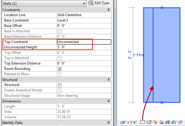
    The 6 feet (or 2 meters) are measured from the top of the bounding box to the bottom of the primary view range. For example, if you create a wall whose top is 6 feet above the bottom clip plane, the wall is cut at the cut plane. When the top of the wall is less than 6 feet, the entire wall shows as projection even where it intersects the cut plane. This behavior always occurs when the Top Constraint property for the wall is specified as Unconnected.

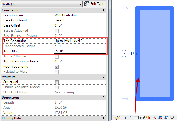
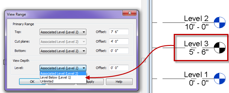
However if you read into the help file it is only when the wall is Unconnected, so if the wall goes to a level set at the given height or in the image below to a level above with a negative Top Offset then the wall will display as if it were being cut. This can be seen by the different thickness of the lines below as well as the expected display of not seeing the additional layer of the wall.

Wall_Unlocked_Cut


Revit 2015 R2 Structural Framing Quirk

With the release of Revit 2015 R2 one of the big features for structural engineers was the capability to flip framing members.  A simple right click on the member and the option to “Flip Structural Framing Ends” appears.  This was a welcome addition and a nice feature to have, but be careful, there are some quirks involved with this feature.  This feature is in reality rotating the beam 180degrees while keeping some of it’s properties relative to the end and others not.

Revit_2015R2_StructuralFraming_Flip_03

Here are some of the quirks I have found to be associated with this new feature.

  • If one end of the beam is utilizing the “Attachment” value it will either be flipped or removed
  • Face based objects hosted to the beam will rotate with the beam and end up on the other side of the beam
  • Adaptive components hosted to the beam will either be rotated or simply disappear
  • When flipping sloped beams they can become detached from their work plane (not like this warning is rare)
  • Cross section rotation will become a negative value keeping it’s relation to vertical (nice catch programmers)

In the images below the plate that host the clevis and rod is the OOTB gusset plate family which is a faced based element, the red connection plate at the top is an adaptive component family.

Revit_2015R2_StructuralFraming_Flip_01

As you can see in the image below the beam rotates when flipped thus creating havoc on elements that are hosted to it.

Revit_2015R2_StructuralFraming_Flip_02

Conclusion to this feature is to be careful when flipping beams and verify elements aren’t hosted to them.

Revit Basics – View Range

Over the years I have had the question come up on why a level can’t be used as an underlay or be selected for view depth or bottom while in the View Range command.  ONLY levels with a view associated to them can be used in these situations.  If a level needs be generated and used for one of these options just add a plan view, so it can be used.

Level_NoView

Generic Annotation Bug

While working with a family to resemble a Level head for detailing I noticed a quirk when dealing with Generic Annotations and justified text.  I had nested in a Generic Annotation family that only had a right justified label, this was nested into another generic annotation family.  What I discovered is right justified labels in a generic annotation family will end up moving the control point if there isn’t a line in the family.  This is odd because when the label is center or left justified the insertion point remains constant.  I traced this issue back to Revit 2012, can’t believe I hadn’t discovered this issue previously.

Generic_Annotaion_Quirk

To resolve this situation a line needs to be added to the family, I personally just added an invisible line on the vertical reference plane, such that it was easier to find if the label was blank.


Scope Box Quirk

When placing scope boxes they will come up with a default name Scope Box ??, where the question marks are a number.  If you rename a scope box to say Area 01 then use the scope box command to place a new one, it will come up with the name Scope Box ??.  However if you copy a scope box it will have a value one higher than the previous, so a copy of Area 1 will be Area 2, the same is true if the name was Area A it will be Area B.  So if there are going to be a multitude of scope boxes on the project think about renaming the first one and copying it around, easier to adjust shape than rename, or at least that is how I do it.