Tag Archives: Floors

Waffle Slab

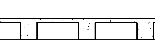
I have been asked many times about the best way to model a waffle slab in Revit.  There are many different ways to go about it; I will discuss a few of them. 

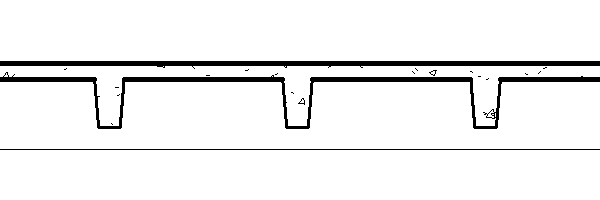
Beams and Floor:  I personally like to model a waffle slab with a floor that is the top thickness and then just draw in the beams for the waffle part.  Either using a rectangular beam or a Pan Joist depending on the construction of the waffle.  I like this method due to the fact that it has the fewest faces modeled in the project.  Each beam will have 6 faces and the slab 6 faces, which is the easiest for Revit to process.


Floor with Holes and Floor:  A lot of users will model one floor that is the thickness of the waffle portion of the slab with holes sketched for the waffles, then model another floor on top of it the solid thickness.  Once both of the the slabs are modeled they will have to be joined together  This method works well if the waffle slab has a varying pattern, but can only have vertical waffles.  The downside to this method is for every opening in the slab there will be 4 additional faces, there for creating more information for Revit to process.

Floor with Custom Void Family:  Lastly, one could create a custom family that is floor based and contains a void.  Change the shape and size of the family(ies) once loaded and place them where needed.  This option is the most flexible and will allow the waffle to do have any shape, however it also creates the most faces.  The voide will have 6 faces which will cut the floor creating 5 addtional faces.  So there will be 11 faces at each waffle taking additional processing power.

Either way you choose here are a few of the options that I have seen used in the industry.

Adaptive slab edge

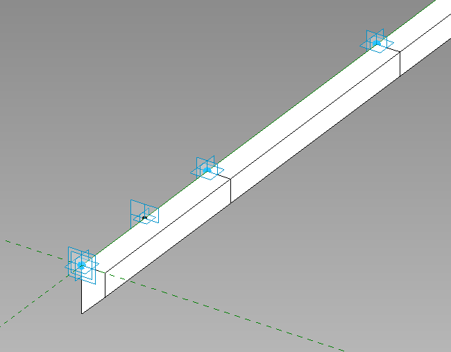
While training a client today the question had come up of how do you do a slab edge when the slab isn’t flat?  This can always be done as an inplace family sweep with a defined profile, but as we all know to many in-place families have a tendency to slow Revit down.  So we went through the process of creating an adaptive family.  The only complaint I have is the limited categories that adaptive components can be, so in this case we left it as a generic model so that it can host rebar.

Start with the Generic Model Adaptive  template, then change the category if desired, we left ours as a generic model. 

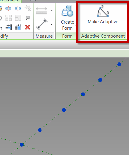
Place ref-points as needed in the view, select the ref-points and change them to adaptive in the contextual ribbon.

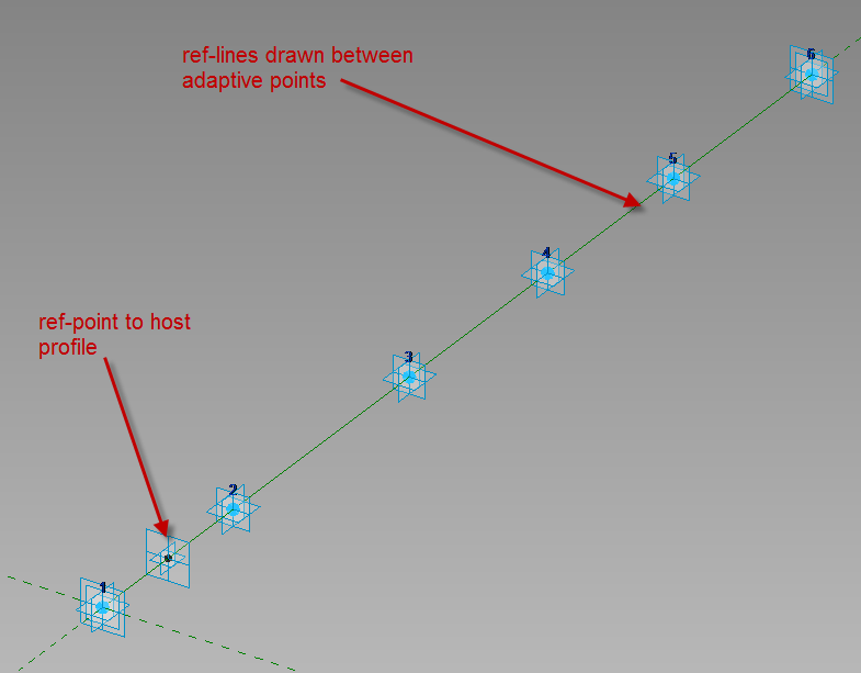
Draw ref lines from the first adaptive point to the second to the third etc., make sure 3D Snapping is on before drawing.  Next draw one ref-point on the ref-line, this point will be used to host the profile.

Since profile families can’t be used inside of an adaptive family create a generic model using model lines to be the profile of the thickened slab, load that into the family and place it on the ref-point.  Select the profile family and map the parameters to parameters in the adaptive family.  Select the profile and the ref-lines then create form.

This is what we had come up with instead of in-place families.  Comment if this works for you or not.


Quick floor sketching method

About a year ago I read a blog that talked about using ceilings as floors in order to utilize the easy auto sketch option with ceilings.  Most of the time I disagree with using tools for things that which they aren’t meant, assuming there is a simple way to use the correct tool.  That post, however, did get me thinking…

Quick side note: Normally when I explain any sketch tool in Revit I stress that using Pick Walls (or Pick Supports) associates the edge of a sketch to a wall (or structural framing member) such that if the wall moves the skethed element also moves.  However, the pick wall tool will only allow a user to pick one wall face, what if the floor is a finish floor, and the sketch lines need to be on each side of the wall.

… when skething a ceiling, there is an “Auto Ceiling” command.  This tool allows a user to pick within a boundary of walls to create all of the sketch lines.  The sketch lines become associated to the walls, similar to “Pick Wall”, such that if the wall moves, the ceiling adjusts with the wall.  I, along with numerous others, have complained for years that there should be an option like this for floors.  When reading that post I thought, what if I copied the sketch lines to the clipboard from an existing ceiling and pasted them into the sketch mode of a floor?  I tried this method, and it worked.  However, there was an issue that kept occuring, which was a circular chain of references.  Somehow when using this copy and paste method the floor occasionally linked itself to the ceiling, so I couldn’t edit or delete one with out it affecting the other.  Feeling slightly defeated, but not ready to throw in the towel, I tried a similar method, but started by creating a new ceiling and then copied the “Auto Ceiling” sketch lines to the clipboard, cancelled the ceiling command, and then used Paste “Align to Current View” to paste the sketch lines into the sketch mode of a floor.  Once I used this approach, the  circular chain of references was no longer an issue.  This method works great for finish floors, as well as slab on grade, where walls need to pass through the slab.

Revit Floors Room Bounding

On Monday Steve Stafford posetd about how finish floors can do bad things when passing a model off to the MEP consultants.   I have also seen this cause issues when the architects go to tag their rooms and and the tag won’t display the room information.  The same situation is true as Steve had posted, all finish floors should be non “Room Bouding” in the Revit model.

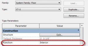
As a good practice I will have architects set the “Function” to all finish floors to be Interior.

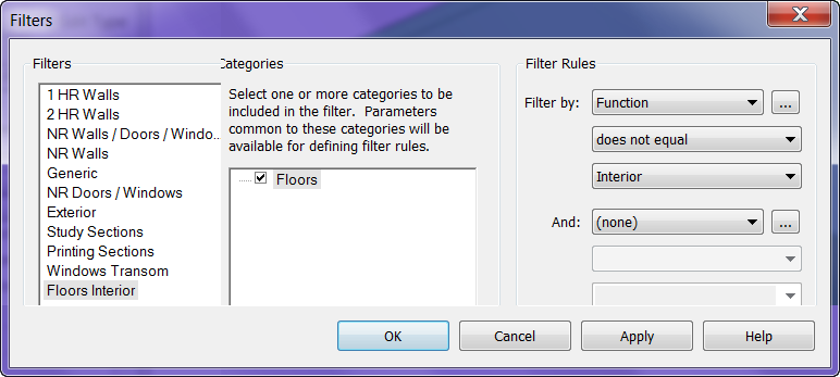
Now that this is set I will create a “Filter” so that it’s “Funtion – does not equal – Interior”.  Then I apply this filter to a 3D view where I turn off the visibility of the filter and only have floors displayed.  Now I can just select all the floors in the view and turn off  the Room Bounding check mark.