One quick dimension tipis a simple way to dimension all grid lines along an axis. Draw a wall outside of the building, making sure it crosses over all of the grid lines that need to be dimensioned. Now use an aligned dimension, and in the options bar change the Pick: value from Individual References to Entire Wall. Click the options button and check Intersecting Walls. Then select the wall and place the dimensions. Now delete the wall and the dimension will remain.
If there is a need to remove only a portion of a dimension string while keeping the string continuous, then right click on a the middle grip on the witness line and select Delete Witness Line. If the need arises to break the string apart, then TAB to select the individual string shape handle and delete that portion of the string as normal.

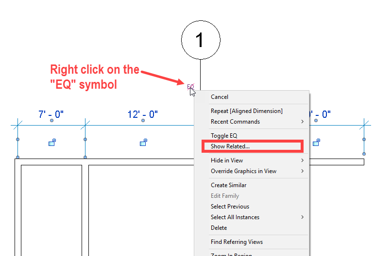
Ever had a dimension and been unclear as to what was actually dimensioned? If so there isn’t any need to start clicking elements on the screen to see if the dimension turns blue. Instead right click on the padlock, regardless of if it is locked or not, and select “Show Related”.

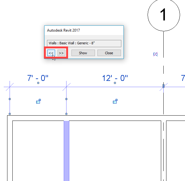
This will bring up a dialog box that will have options to cycle through the two objects that are being dimensioned by that dimension segment.

When a dimension text value is moved from its’ origin, there is a tool to move it back to the original position. Select the dimension string, right click and select Reset Dimension Text Position.

A classic dimension tip is how to use dimensions to move/alter the element it is dimensioning. If a dimension is applied to an element then selecting the element will activate the dimension and it the dimension value can be changed. Furthermore if the dimension type is set to fractional inches, or millimeters then those values can be used for input, instead of having to input feet or meters (ie type “6” instead of ”0’ – 6”, “0.5” or “100” instead of 100mm, “0.1”).