Tag Archives: Basics

Copy Parameters from one family to another

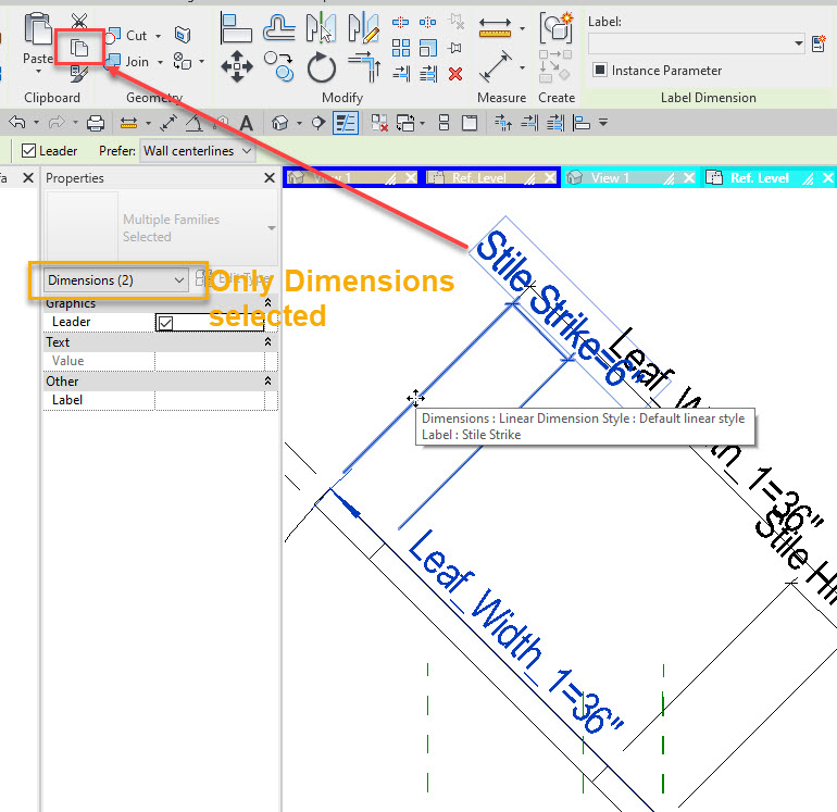
Over the years I have tried several ways to copy parameters from one family to another. I have created solids or reference planes added dimensions and then copied all of that to the clipboard, then pasted to another family, and deleted what was pasted. I have used Dynamo and other add in tools as well. This week I realized you can simply copy the dimension, then paste into the other family. No need to go back and delete everything as nothing will actually paste but the parameter names.

Revit Basics – Group Origin Points

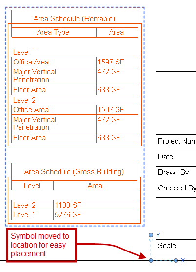
I am not a big fan of groups I tend to think they get over used in lieu of families, but this post isn’t going to get into that.  With that said there is a time and place for their use and when they are being used I think there are a couple of tips that I see commonly overlooked.  The simplest tip to discuss is the groups origin point.  When a group is created it will place a symbol in the center of the objects being grouped, this symbol is the origin point.  This symbol is used not only for the origin point when placing the group but also as the origin when the group is being changed from one type to another.  To adjust where this is located simply select the group and drag the symbol to a location that is better than the random center(ish) area of the group.  This way placement of the group is easier as well maintaining it’s placement when the group type is changed.

Group_InsertionPoint

In the image above a group was created for alignment of several schedules onto sheets, the “Group Origin” was moves such that is could easily be snapped to the title block.

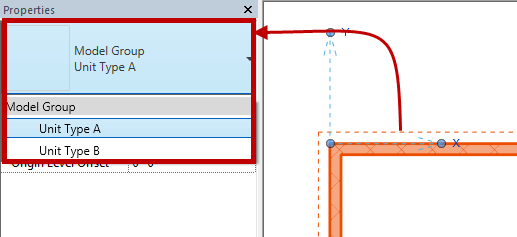
Another tip is the fact that groups can be changed just liked any family.  If a group is selected it can the be changed via the “Type Selector” just like any family.  This is why it is important to pay attention to the “Group Origin” as stated above.

Group_TypeSelector

Last tip for the day is if you are only using a group one time consider ungrouping it and purging the group out of the model.  It is a known fact that groups will slow Revit down especially when they are over used.

Instance based Family System Parameters

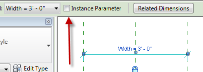
A question came up on how to change a family system parameter from Type based to Instance based.  It made me think of the good old days when we had to start a family, say structural foundation or door family, change it to a generic model family, go into the family types and modify the values from Type to Instance then change the family type back to the original category.  Good news is this changed way back, now all you have to do is select a dimension with this value and toggle the check box in the options bar to Instance.

Framing Orientation

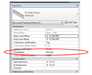
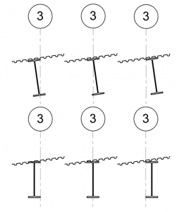
This is one of those Revit basics that has been forgotten, or perhaps never learned.  In the instance parameters for structural framing members, there is a parameter called “Orientation”.

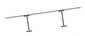
The framing member is only affected by this property if it was modeled on a sloped work plane.

The default orientation is normal – normal to the work plane.

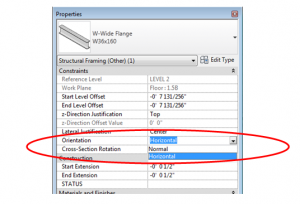
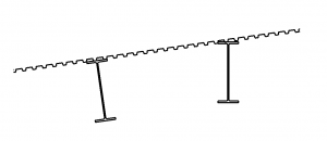
If the orientation is changed to horizontal, the beam will rotate such that the flanges are horizontal.

One item of note is that the rotation point is at the intersection of the top of the beam and the lateral justification (Side 1, Center, or Side 2), so if perfect accuracy is required, the beam may have to be shifted down.  The screen shot below shows how the different combinations of a horizontal orientation interacts with the Lateral Justification.


Revit Basics – Linework Tool

The linework tool is found on the Modify tab, in the View panel.
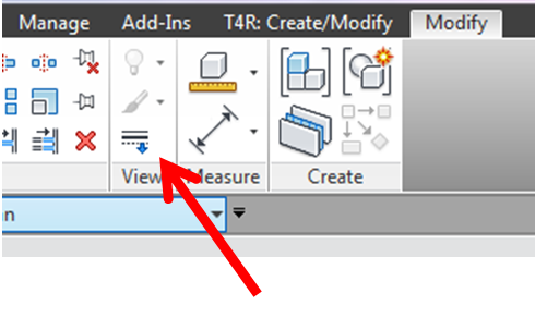
 

With this tool a Revit user can override the graphical style of a model element, i.e. change something from a solid to a dashed or hidden line, or to make a line invisible all together.  Any line style in the project may be used, plus a few default out-of-the-box options.  Furthermore, each edge, side or line of an element may be independently overridden (so only one side of a wall, or one edge of a slab, etc). 

Once a line is overridden grips will appear at the ends of the lines.  These grips can be drug one way or another such that only part of the line is overridden.  The catch is that these grips will only appear when the linework tool is activated, and when the overridden line is selected.
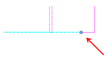
 

What if more than one portion of a line is to be overridden?  Use the line work tool again and additional grips will appear that can now be drug independently from the first set.

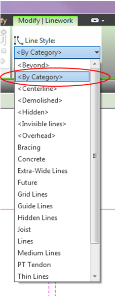
  

One final question with this tool is how would one put the element back to its default style?  No, one would not have to delete the element and remodel it, and it is never a good idea to just draw lines over it.

 The answer is to use the linework tool once again, but instead of choosing a line style, choose “By Category” and click on the elements to be changed back to their default style. (It will be possible to select only overridden elements, even the ones that were made invisible).