
For a few releases now Revit has had the capability to model composite decks with 2D graphics to display the metal deck when in sections. While working with a client the question came up on what determines the line weights / line types in views. After some trial and error I was able to determine what is happening with these lines. When the section is perpendicular the deck, nothing special the line weights are simply controlled by the Floor category and the Section styles, however it is a different story when cutting parallel to the deck.
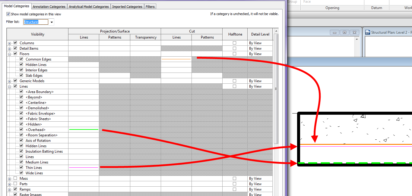
The line that shows the transition from the layer above to the metal deck (shown orange below) is the subcategory Common Edges under Floors
The line that is representing the underside of the top of the metal deck (shown magenta below) uses the subcategory Thin Lines under the Lines category
The line that represents the top of the lower portion of the metal deck (shown green below) uses the subcategory Overhead under the Lines category
Thanks for figuring this out! My question is, if you wanted to change those linetypes, is it going to affect other families also?
If you change them in the object styles then yes it can affect the entire project and more than likely things even I am unaware of. I would suggest changing these in Visibility Graphics if it is something that needs changing. Or setting up a view template for composite decks in cross section, that way it can just be applied in the cases where it is needed.