
I have had some questions come up about dimensioning sloped framing, so I thought it deserved a blog post.
Question: Why can’t I dimension to framing members when they are associated to a sloped work plane?
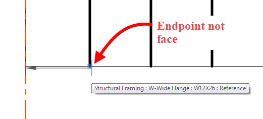
- This question comes up when attempting to dimension in plan, in a coarse level of detail, when the framing member is Normal to the work plane, and when using the Linear Dimension option. Beams can be selected using the linear option, however the user won’t be selecting a face, since it isn’t perpendicular to the view, they will be selecting the end point of the graphic line.
- Make sure when dimensioning the endpoint of the beam is being selected and not a face. It is sometimes hard to see but a grip will come up, along with a tool tip, when the end of the beam is selected.
Question: Why aren’t my dimensions equal in plan and section?
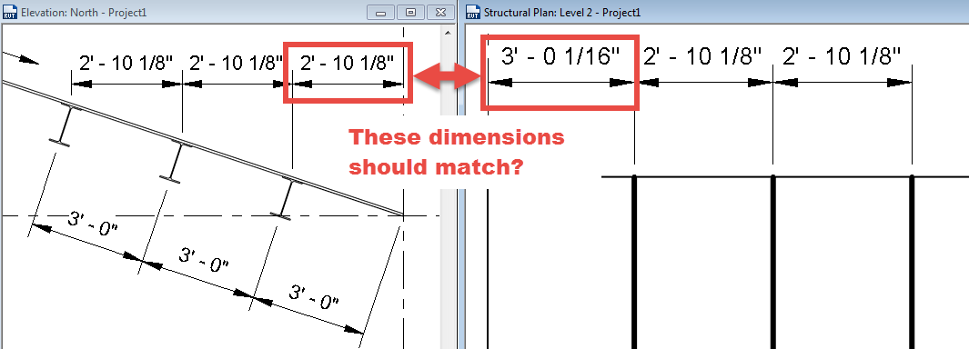
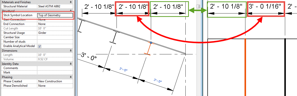
- This issue is due to the location of the symbolic line of the framing member. In the elevation above the beam was dimensioned to the Top Midline, however the default setting for “Stick Symbol Location” is set to “Center of Geometry”, thus making the stick symbol location in plan different then in elevation. Depending on how the family is created this property may only affect the plan and not any of the other views.
- Selecting the framing member and changing the “Stick Symbol Location” value to “Top of Geometry” will insure that the plan dimension is the same as the elevation dimension. However, it will need to be changed for all of the elements being dimensioned.
I hope this helps clear up these two common questions. If anyone has other tips about these please comment.
great tutorial.
That is a question that comes up a lot I am glad you found it informative