Category Archives: Architecture

Revit Architecture topics

Adaptive Component – Everyday Uses part 3

Continued from..

Adaptive Component – Everyday Uses part 2
Adaptive Component – Everyday Uses part 1

Creating Forms

Unlike the normal family editor, in adaptive and mass families, surfaces and solids can be created.  These are created using the Create Form button and not extrusions, sweeps, etc..  Unfortunately points cannot be used to create elements, reference lines and/or model lines must be used for this task.  Lines can be used if they are part of the rig, however, if additional lines are required, then they need to be created prior to creating solids or surfaces.  In the adaptive (as well as mass) family environment, surfaces can be created from a single line or from multiple lines.

Surfaces and Extrusions

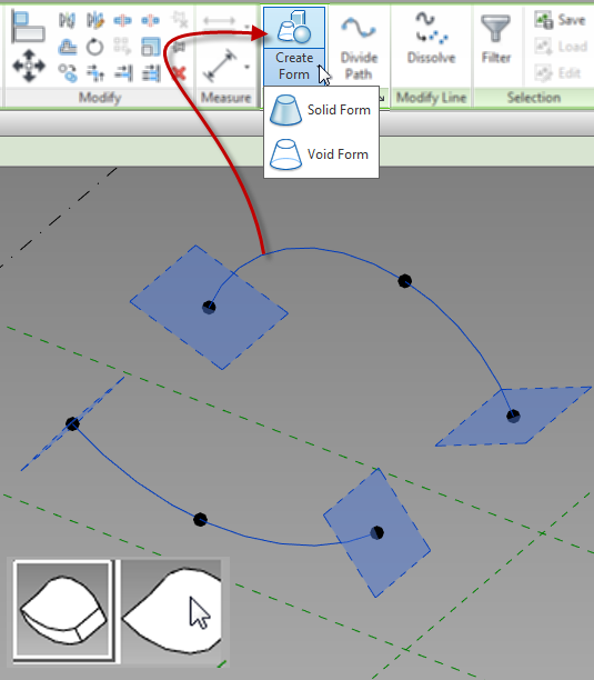
To create a solid or surface, select the desired lines and select the Create Form button.  Voids can be created in the same manner.  If Revit can determine more than one way to create a solid, or if it can create a surface, different images will appear on the screen allowing a user to select the appropriate one.

CreateForm

Sweeps

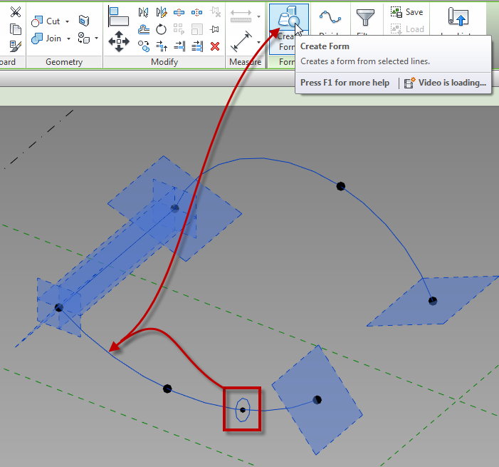
A sweep is created by drawing lines for the shape of the sweep, then by selecting those and the lines that represent the path.  Once all of the elements are selected, use the create form button to create the sweep.

CreateForm_Sweep

Revolves

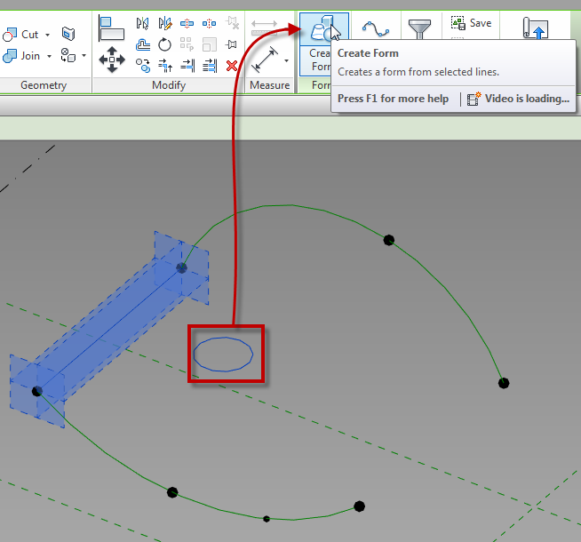
A Revolve is created by selecting a group of lines or arcs that are all parallel to a single line.  This one line acts as an axis.

CreateForm_Revolve

Once surfaces or solids have been created, their faces and edges can be used to generate additional forms.  For example, the edges of a cube can then be used for the path of a sweep, or the edge of a surface can be used to generate an additional surface.

Up next…

Adaptive Component – Everyday Uses part 4


Wall Display Quirk

Steve Stafford posted about this quirk back in 2012 but I have had the question come up several times in the past month so I thought it would be worth bringing this topic up again.

When building a wall with multiple layers built up it is possibly to unlock layers of the wall such that they can be raised or lowered independently of the rest of the wall (the property exposed is “Base Extension Distance” or “Top Extension Distance”).  This feature is invaluable when the need to have a wall finish go above or below the base of the wall, or if the need arises to have the wall modeled up to the structure yet have the gypsum stop short.  However when a layer has been unlocked and that wall is a partial height wall** then Revit will ignore the coarse level of detail and display the unlocked layers of that wall type.

Wall_Unlocked_Quirk_01

**per the Revit help a partial height wall is defined as

  • Walls shorter than 6 feet (or 2 meters) are not cut, even if they intersect the cut plane.

    The 6 feet (or 2 meters) are measured from the top of the bounding box to the bottom of the primary view range. For example, if you create a wall whose top is 6 feet above the bottom clip plane, the wall is cut at the cut plane. When the top of the wall is less than 6 feet, the entire wall shows as projection even where it intersects the cut plane. This behavior always occurs when the Top Constraint property for the wall is specified as Unconnected.

However if you read into the help file it is only when the wall is Unconnected, so if the wall goes to a level set at the given height or in the image below to a level above with a negative Top Offset then the wall will display as if it were being cut. This can be seen by the different thickness of the lines below as well as the expected display of not seeing the additional layer of the wall.

Wall_Unlocked_Cut


Spot Slope Revit

While helping set up a template with a client there was a discussion on how the graphic should look for the spot slope symbol, hence this post.

While  placing a spot slope there is an option to change the graphic representation to be either Arrow or a Leader.  However this option is not available in a plan, only vertical views such as sections.  This can also be done after placement in the properties dialog.

SpotSlopeTriangle

The type properties for spot slopes also allow for more options and variations on the display as well as the units:

  • Slope Direction allows for the slope to point down or up, however if the triangle option is used then it just changes the insertion point
  • Leader line Length changes the length of both the arrow and the triangle option
  • Similar to other dimension types the units format can be changed.  With slopes some firms like to display roof slopes with a Ratio/12 while displaying sloping floors with a ration or percentage.  By duplicating the slope type all of these options can be available.
  • Using alternate units will allow for Ratio as well as percentage or whatever combination in needed

SpotSlopeProperties

Revit Structural Deck Line Types

For a few releases now Revit has had the capability to model composite decks with 2D graphics to display the metal deck when in sections.  While working with a client the question came up on what determines the line weights / line types in views.  After some trial and error I was able to determine what is happening with these lines.  When the section is perpendicular the deck, nothing special the line weights are simply controlled by the Floor category and the Section styles, however it is a different story when cutting parallel to the deck.

The line that shows the transition from the layer above to the metal deck (shown orange below) is the subcategory Common Edges under Floors

The line that is representing the underside of the top of the metal deck (shown magenta below) uses the subcategory Thin Lines under the Lines category

The line that represents the top of the lower portion of the metal deck (shown green below) uses the subcategory Overhead under the Lines category

Composite_Deck_LineStyles

RTC 2014

My blog has gone dark for a while in case you didn’t know my family was blessed with a beautiful baby girl, aka #BIMbino. I was planning on taking a break for a while and then start blogging again once she started sleeping through the night.  Since this hasn’t happened yet and I don’t envision this happening anytime soon I decided it was time to start up again, however I doubt I will be blogging as often as before the BIMbino.  What better of an excuse to get me started than Revit Technology Conference.

This year at RTC I was privileged to speak in three sessions.  This isn’t the reason I am blogging I also attended some great sessions taught by excellent well known speakers.

One of the sessions I enjoyed was based on Navisworks and quatification taught by Jason Dodds.  This session covered the takeoff tools, creating and importing catalogs.  Jason also did a great job explaining the difference from when these tools were in Autodesk QTO.

Another session was taught by Andy Milburn where he covered mass families where he has developed a few different ways of making rigs to create content.  I personally like his box theory and using an invisible box as a rig platform.

Havard Vasshaug taught a two part lab on computational logic in structure.  Unfortunately I was only able to attend half of this session but what I saw was great.

I got to finish up the conference on the main stage for the redesigned Tips & Trick led by Desiree Mackey.  In the past a they have presented slides based on tips from different sessions taught, this year they decided to a battle of the tips, complete with a gong.  There were two teams myself, Amy Manning and Matt Nelson vs Zack Kron, Scot Brown and Nick Hugley and we had to present some tips from the sessions while being able to add in some of our own.  If the panel, Jim Balding or Wesley Benn decided you were stumbling, didn’t like the tip or just wanted to hear a loud noise they would with the 3 foot (91cm) GONG and you had to move on.  I thought it was a new fun way to present the tips and it did get the audience involved which for me was very fun.  Although we did win some considered bringing two babies on stage was a bit of cheat.

With that said the North American conference was well worth the time and the information one can get from it makes it a must attend event.  I am looking forward to speaking and attending RTC Europe in Dublin over Halloween.